RM 38.00 – RM 55.00Price range: RM 38.00 through RM 55.00
Phoenix Contact develops terminal blocks, distribution blocks, power supplies, relays, connectors, signal conditioners, controllers & PLCs, I/O systems, Industrial Ethernet, controller system cabling, PCB terminal blocks & connectors, and surge suppression.
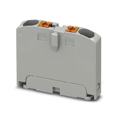
Distribution block, Basic terminal block, nom. voltage: 450 V, nominal current: 24 A, connection method: Push-in connection, cross section: 0.14 mm² – 4 mm², mounting type: for snapping onto a DIN rail adapter, Direct mounting with flange, Free-hanging, color: gray
| Part Number | 1028067 |
|---|---|
| Number of rows | 1 |
| Number of connections | 2 |
| Potentials | 1 |
| Nominal cross section | 2.5 mm² |
| Color | gray |
| Insulating material | PA |
| Flammability rating according to UL 94 | V0 |
| Mounting type | for snapping onto a DIN rail adapter |
| Rated surge voltage | 6 kV |
| Degree of pollution | 3 |
| Overvoltage category | III |
| Insulating material group | I |
| Maximum power dissipation for nominal condition | 0.77 W |
| Maximum load current | 27 A |
| Nominal current IN | 24 A |
| Nominal voltage UN | 450 V |
| Open side panel | No |
| General information | The maximum load current of a single clamping unit must not be exceeded. |
| Shock protection test specification | DIN EN 50274 (VDE 0660-514):2002-11 |
| Back of the hand protection | guaranteed |
| Finger protection | guaranteed |
| Result of surge voltage test | Test passed |
| Result of power-frequency withstand voltage test | Test passed |
| Power frequency withstand voltage setpoint | 1.89 kV |
| Result of the test for mechanical stability of terminal points (5 x conductor connection) | Test passed |
| Result of flexion and pull-out test | Test passed |
| Bending test rotation speed | 10 rpm |
| Bending test turns | 135 |
| Bending test conductor cross section/weight | 0.14 mm² / 0.2 kg |
| 2.5 mm² / 0.7 kg | |
| 4 mm² / 0.9 kg | |
| Tensile test result | Test passed |
| Conductor cross section tensile test | 0.14 mm² |
| Tractive force setpoint | 10 N |
| Conductor cross section tensile test | 2.5 mm² |
| Tractive force setpoint | 50 N |
| Conductor cross section tensile test | 4 mm² |
| Tractive force setpoint | 60 N |
| Result of tight fit on support | Test passed |
| Tight fit on carrier | NS 35 |
| Setpoint | 1 N |
| Note | When aligning several blocks, the foot elements should be placed in a way that maximum 5 blocks are free-hanging in between. Flange elements should be placed after every 9 blocks. |
| Depending on the application case and mechanical load, other arrangements of the mounting accessory can also be chosen. | |
| One DIN rail adapter PTFIX-NS35 is intended for maximum 11 blocks. | |
| Result of voltage-drop test | Test passed |
| Result of temperature-rise test | Test passed |
| Requirement temperature-rise test | Increase in temperature ≤ 45 K |
| Short circuit stability result | Test passed |
| Conductor cross section short circuit testing | 2.5 mm² |
| Short-time current | 0.3 kA |
| Conductor cross section short circuit testing | 4 mm² |
| Short-time current | 0.48 kA |
| Result of thermal test | Test passed |
| Proof of thermal characteristics (needle flame) effective duration | 30 s |
| Result of aging test | Test passed |
| Ageing test for screwless modular terminal block temperature cycles | 192 |
| Oscillation, broadband noise test result | Test passed |
| Test specification, oscillation, broadband noise | DIN EN 50155 (VDE 0115-200):2008-03 |
| Test spectrum | Service life test category 2, bogie-mounted |
| Test frequency | f1 = 5 Hz to f2 = 250 Hz |
| ASD level | 6.12 (m/s²)²/Hz |
| Acceleration | 3.12g |
| Test duration per axis | 5 h |
| Test directions | X-, Y- and Z-axis |
| Shock test result | Test passed |
| Test specification, shock test | DIN EN 50155 (VDE 0115-200):2008-03 |
| Shock form | Half-sine |
| Acceleration | 30g |
| Shock duration | 18 ms |
| Number of shocks per direction | 3 |
| Test directions | X-, Y- and Z-axis (pos. and neg.) |
| Relative insulation material temperature index (Elec., UL 746 B) | 130 °C |
| Temperature index of insulation material (DIN EN 60216-1 (VDE 0304-21)) | 130 °C |
| Static insulating material application in cold | -60 °C |
| Surface flammability NFPA 130 (ASTM E 162) | passed |
| Specific optical density of smoke NFPA 130 (ASTM E 662) | passed |
| Calorimetric heat release NFPA 130 (ASTM E 1354) | 28 MJ/kg |
| Smoke gas toxicity NFPA 130 (SMP 800C) | passed |
| Fire protection for rail vehicles (DIN EN 45545-2) R22 | HL 1 – HL 3 |
| Fire protection for rail vehicles (DIN EN 45545-2) R23 | HL 1 – HL 3 |
| Fire protection for rail vehicles (DIN EN 45545-2) R24 | HL 1 – HL 3 |
| Fire protection for rail vehicles (DIN EN 45545-2) R26 | HL 1 – HL 3 |
| Width | 5.2 mm |
|---|---|
| Length | 28.6 mm |
| Height | 21.7 mm |
| Connection method | Push-in connection |
|---|---|
| Stripping length | 8 mm … 10 mm |
| Connection in acc. with standard | IEC 60998-2-2 |
| Conductor cross section solid min. | 0.14 mm² |
| Conductor cross section solid max. | 4 mm² |
| Conductor cross section AWG min. | 26 |
| Conductor cross section AWG max. | 12 |
| Conductor cross section flexible min. | 0.14 mm² |
| Conductor cross section flexible max. | 2.5 mm² |
| Min. AWG conductor cross section, flexible | 26 |
| Max. AWG conductor cross section, flexible | 12 |
| Conductor cross section flexible, with ferrule without plastic sleeve min. | 0.14 mm² |
| Conductor cross section flexible, with ferrule without plastic sleeve max. | 2.5 mm² |
| Conductor cross section flexible, with ferrule with plastic sleeve min. | 0.14 mm² |
| Conductor cross section flexible, with ferrule with plastic sleeve max. | 2.5 mm² |
| Connection cross sections directly pluggable | 0.34 mm² 4 mm² 24 12 |
| Conductor cross section solid min. | 0.34 mm² |
| Conductor cross section solid max. | 4 mm² |
| Conductor cross section AWG min. | 24 |
| Conductor cross section AWG max. | 12 |
| Conductor cross section flexible, with ferrule without plastic sleeve min. | 0.34 mm² |
| Conductor cross section flexible, with ferrule without plastic sleeve max. | 2.5 mm² |
| Conductor cross section flexible, with ferrule with plastic sleeve min. | 0.34 mm² |
| Conductor cross section flexible, with ferrule with plastic sleeve max. | 2.5 mm² |
| Internal cylindrical gage | A3 |
| Operating temperature | -60 °C … 105 °C (max. short-term operating temperature RTI Elec.) |
|---|---|
| Ambient temperature (storage/transport) | -25 °C … 60 °C (for a short time, not exceeding 24 h, -60 °C to +70 °C) |
| Permissible humidity (storage/transport) | 30 % … 70 % |
| Ambient temperature (assembly) | -5 °C … 70 °C |
| Ambient temperature (actuation) | -5 °C … 70 °C |
| Connection in acc. with standard | IEC 60998-2-2 |
|---|
| China RoHS | Environmentally friendly use period: unlimited = EFUP-e |
|---|---|
| No hazardous substances above threshold values |