$ 190.50
Phoenix Contact develops terminal blocks, power supplies, relays, connectors, signal conditioners, controllers & PLCs, I/O systems, Industrial Ethernet, controller system cabling, PCB terminal blocks & connectors, and surge suppression.
| Item number | 2700578 |
| Packing unit | 1 pc |
| Minimum order quantity | 1 pc |
| Product key | DNA182 |
| Catalog page | Page 252 (C-6-2019) |
| GTIN | 4046356916400 |
| Weight per piece (including packing) | 199.8 g |
| Weight per piece (excluding packing) | 182.1 g |
| Customs tariff number | 85364900 |
| Country of origin | DE |
| Note on application | |
| Note on application | Only for industrial use |
| Utilization restriction | |
| CCCex note | Use in potentially explosive areas is not permitted in China |
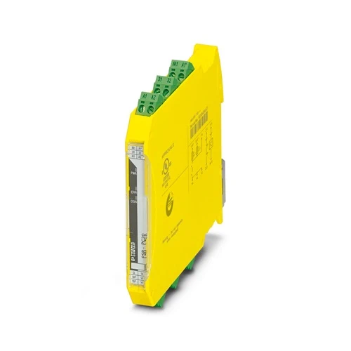
| Product type | Coupling relay |
| Product family | PSRmini |
| Application | Safe switch off |
| High demand | |
| Low demand | |
| Ex | |
| Control | 1-channel |
| Relay type | Electromechanical relay with force-guided contacts in accordance with IEC/EN 61810-3 |
| Insulation characteristics: Air clearances and creepage distances between the power circuits | |
| Overvoltage category | III |
| Degree of pollution | 2 |
| Times | |
| Typ. starting time with Us | < 100 ms (with Us when controlled via A1) |
| Typical release time | < 35 ms (when controlled via A1) |
| Recovery time | 500 ms |
| Maximum power dissipation for nominal condition | 3.43 W (IL² = 36 A²) |
| Nominal operating mode | 100% operating factor |
| Air clearances and creepage distances between the power circuits | |
| Rated insulation voltage | 250 V AC |
| Rated surge voltage/insulation | Safe isolation, 6 kV reinforced insulation from control circuit, start circuit, confirmation current path, signal output to the enabling current path; 4 kV/basic insulation between all current paths and housing |
| Supply | |
| Designation | A1/A2 |
| Rated control circuit supply voltage US | 20.4 V DC … 26.4 V DC |
| Rated control circuit supply voltage US | 24 V DC -15 % / +10 % |
| Rated control supply current IS | typ. 50 mA |
| Power consumption at US | typ. 1.2 W |
| Inrush current | typ. 400 mA (Δt < 10 µs at Us) |
| Filter time | max. 2 ms (at A1-A2; test pulse width) |
| ≥ 100 ms (at A1-A2; test pulse rate) | |
| Protective circuit | Serial protection against polarity reversal; Suppressor diode 33 V |
| Supply | |
| Designation | 31/A2, TBUS |
| Diagnostic supply voltage UD | 24 V DC -15 % / +10 % |
| Input current at UD | 6 mA (at 31-A2 for UD; depending on load + 100 mA at M1 and 32) |
| Inrush current at UD | typ. 2.5 A (Δt < 20 µs at UD) |
| Protective circuit | Serial protection against polarity reversal; Suppressor diode 33 V |
| Relay: Enabling current path (13/14 (13F/14)) | |
| Output description | 2 N/O contacts in series, without delay, floating |
| Number of outputs | 1 (safety-related) |
| Contact switching type | 1 enabling current path |
| Contact material | AgSnO2 |
| Switching voltage | min. 12 V AC/DC |
| max. 250 V AC/DC | |
| Switching capacity | min. 60 mW |
| Inrush current | min. 3 mA |
| max. 6 A (N/O contact 13/14) | |
| 4 A (N/O contact 13F/14) | |
| Switching capacity in accordance with IEC 60947-5-1 | 4 A (24 V (DC13); N/O contact 13/14) |
| 5 A (250 V (AC15); N/O contact 13/14) | |
| 4 A (250 V (AC15); N/O contact 13F/14) | |
| Limiting continuous current | 6 A (13/14 for high-demand) |
| 4 A (13F/14 with high/low demand, 13/14 with low demand) | |
| Sq. Total current | 36 A2 (13/14, see to derating) |
| 16 A2 (13F/14, see to derating) | |
| Switching frequency | max. 0.1 Hz |
| Mechanical service life | 10x 106 cycles |
| Output fuse | 6 A gL/gG (N/O contact 13/14) |
| 4 A gL/gG (for low-demand applications) | |
| Relay: Confirmation current path (31/32) | |
| Output description | 2 N/C contacts in series, without delay, not floating (reference ground: A2) |
| Number of outputs | 1 (safety-related) |
| Contact switching type | 1 confirmation current path |
| Contact material | AgCuNi, + Au |
| Switching voltage | min. 20.4 V DC |
| max. 26.4 V DC | |
| Switching capacity | min. 20 mW |
| Inrush current | min. 1 mA |
| max. 100 mA | |
| Limiting continuous current | 100 mA |
| Switching frequency | max. 0.1 Hz |
| Mechanical service life | 10x 106 cycles |
| Output fuse | 150 mA Fast-blow |
| Signal: M1 | |
| Output description | PNP |
| Number of outputs | 1 (non-safety-related) |
| Voltage | approx. 22 V DC (UD – 2 V) |
| Current | max. 100 mA |
| Maximum inrush current | 500 mA (Δt = 1 ms at Us) |
| Short-circuit protection | no |
| Output fuse | 150 mA fast blow |
| Connection technology | |
| pluggable | yes |
| Conductor connection | |
| Connection method | Push-in connection |
| Conductor cross section rigid | 0.2 mm² … 1.5 mm² |
| Conductor cross section flexible | 0.2 mm² … 1.5 mm² |
| Conductor cross section, flexible, with ferrule, with plastic sleeve | 0.25 mm² … 1.5 mm² (only together with CRIMPFOX 6) |
| Conductor cross section flexible, with ferrule without plastic sleeve | 0.25 mm² … 1.5 mm² (only together with CRIMPFOX 6) |
| Conductor cross-section AWG | 24 … 16 |
| Stripping length | 8 mm |
| Status display | 1 x LED (green) |
| Operating voltage display | 1 x LED (yellow) |
| Error indication | 1 x LED (red) |
| Width | 12.5 mm |
| Height | 116.6 mm |
| Depth | 114.5 mm |
| Color (Housing) | yellow (RAL 1018) |
| Housing material | PA |
| Safety data | |
| Stop category | 0 |
| Safety data: EN 50156 | |
| Safety Integrity Level (SIL) | 3 |
| Safety data: IEC 61508 – High demand | |
| Safety Integrity Level (SIL) | 3 |
| Safety data: IEC 61508 – Low demand | |
| Safety Integrity Level (SIL) | 3 |
| Ambient conditions | |
| Degree of protection | IP20 |
| Min. degree of protection of inst. location | IP54 |
| Ambient temperature (operation) | -40 °C … 70 °C (observe derating) |
| Ambient temperature (storage/transport) | -40 °C … 85 °C |
| Maximum altitude | ≤ 2000 m (Above sea level) |
| Max. permissible humidity (storage/transport) | 75 % (on average, 85% infrequently, non-condensing) |
| Max. permissible relative humidity (operation) | 75 % (on average, 85% infrequently, non-condensing) |
| Shock | 15g |
| Vibration (operation) | 10 Hz … 150 Hz, 2g |
| ATEX | |
| Identification | II 3G Ex ec nC IIC T4 Gc |
| Certificate | UL 22 ATEX 2912X |
| IECEx | |
| Identification | Ex ec nC IIC T4 Gc |
| Certificate | IECEx UL 22.0037X |
| UL, USA/Canada | |
| Identification | cULus |
| Certificate | E140324 |
| UL Ex, USA / Canada | |
| Identification | Class I, Zone 2, AEx ec nC IIC T4 / Ex ec nC IIC Gc T4 X |
| Class I, Div. 2, Groups A, B, C, D, T4 | |
| Certificate | E360692 |
| CE | |
| Identification | CE-compliant |
| Environmental simulation test | |
| Identification | G3 |
| Certificate | ISA-S71.04 |
| CCC / China-Ex | |
| Identification | Ex ec nC IIC T4 Gc |
| Certificate | 2022122304115695 |
| DNV | |
| Identification | C, EMC2 |
| Certificate | 11253-14 HH |
| Air clearances and creepage distances between the power circuits | |
| Standards/regulations | EN 60664-1, EN 60079-7, EN 60079-15 |
| Mounting type | DIN rail mounting |
| Assembly note | See derating curve |
| Mounting position | vertical, horizontal, with front of module upward |