| Unit name | Safety Input Unit | |
|---|---|---|
| Model | NX-SIH400 | NX-SID800 |
| Number of safety input points |
4 points | 8 points |
| Number of test output points |
2 points | 2 points |
| Internal I/O common | PNP (sinking inputs) | |
| Rated input voltage | 24 VDC (20.4 to 28.8 VDC) | |
| OMRON special safety input devices |
Can be connected. | Cannot be connected. |
| Number of safety slave connections |
1 | |
| I/O refreshing method | Free-Run refreshing | |
| External connection terminals |
Screwless clamping terminal block (8 terminals) |
Screwless clamping terminal block (16 terminals) |
| Indicators | ||
| Safety input current | 4.5 mA typical | 3.0 mA typical |
| Safety input ON voltage |
11 VDC min. | 15 VDC min. |
| Safety input OFF voltage/OFF current |
5 VDC max., 1 mA max. | |
| Test output type | Sourcing outputs (PNP) | |
| Test output load current |
25 mA max. | 50 mA max. |
| Test output residual voltage |
1.2 V max. (Between IOV and all output terminals) | |
| Test output leakage current |
0.1 mA max. | |
| Dimensions | 12 × 100 × 71 mm (W × H × D) | |
| Isolation method | Photocoupler isolation | |
| Insulation resistance | 20 MΩ min. between isolated circuits (at 100 VDC) | |
| Dielectric strength | 510 VAC for 1 min between isolated circuits, leakage current: 5 mA max. | |
| I/O power supply method |
Power supplied from the NX bus | |
| Current capacity of I/O power supply terminals |
No applicable terminals. | |
| NX Unit power consumption |
• Connected to a CPU Unit or a Communication Control Unit *1 1.10 W max. • Connected to a Communications Coupler Unit *2 0.70 W max. |
• Connected to a CPU Unit or a Communication Control Unit *1 1.10 W max. • Connected to a Communications Coupler Unit *2 0.75 W max. |
| Current consumption from I/O power supply |
20 mA max. | |
| Weight | 70 g max. | |
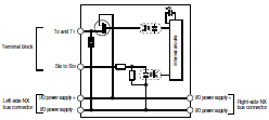
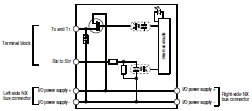
| Circuit layout |  |
 |
| Terminal connection diagram |
Si0 to Si3: Safety input terminals T0 and T1: Test output terminals  Refer to User’s manual (Cat.No.Z930) for details. |
Si0 to Si7: Safety input terminals T0 and T1: Test output terminals  Refer to User’s manual (Cat.No.Z930) for details. |
| Installation orientation and restrictions |
Installation orientation: • Connected to a CPU Unit or a Communication Control Unit *1 Possible in the upright installation orientation. • Connected to a Communications Coupler Unit *2 6 possible orientations. Restrictions: Maximum ambient temperature is 50ºC for any orientation other than upright installation. |
|
| Protective functions | Overvoltage protection circuit and short detection (test outputs) | |
*1 It can be connected to the NX102 CPU unit or communication control unit. It cannot be connected to the NX1P2 CPU unit.
*2 The NX-ECC20 EtherCAT Coupler Unit and NX-EIC202 EtherNet/IP Coupler Unit can be connected.

