| Product name |
Specification | Model | ||||||
|---|---|---|---|---|---|---|---|---|
| CT input section | Control output section | |||||||
| Number of inputs |
Maximum heater current |
Number of outputs |
Internal I/O common |
Maximum load current |
Rated voltage |
I/O refreshing method |
||
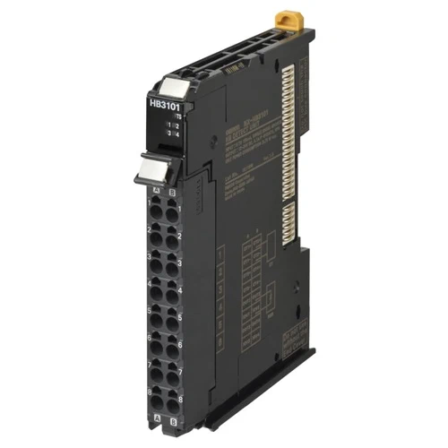
| Heater Burnout Detection Unit |
4 | 50 A AC | 4 | NPN | 0.1 A/point, 0.4 A/Unit |
12 to 24 VDC |
Free-Run refreshing |
NX-HB3101 |
| PNP | 24 VDC | NX-HB3201 | ||||||
| Item | Specification | |
|---|---|---|
| Enclosure | Mounted in a panel | |
| Grounding method | Ground to 100 Ω or less | |
| Operating environment |
Ambient operating temperature |
0 to 55°C |
| Ambient operating humidity |
10% to 95% (with no condensation or icing) | |
| Atmosphere | Must be free from corrosive gases. | |
| Ambient storage temperature |
-25 to 70°C (with no condensation or icing) | |
| Altitude | 2,000 m max. | |
| Pollution degree | 2 or less: Meets IEC 61010-2-201. | |
| Noise immunity | 2 kV on power supply line (Conforms to IEC61000-4-4.) | |
| Overvoltage category | Category II: Meets IEC 61010-2-201. | |
| EMC immunity level | Zone B | |
| Vibration resistance | Conforms to IEC 60068-2-6. 5 to 8.4 Hz with 3.5-mm amplitude, 8.4 to 150 Hz, acceleration of 9.8 m/s2, 100 min each in X, Y, and Z directions (10 sweeps of 10 min each = 100 min total) |
|
| Shock resistance | Conforms to IEC 60068-2-27. 147 m/s2, 3 times each in X, Y, and Z directions | |
| Applicable standards * | cULus: Listed (UL508), ANSI/ISA 12.12.01, EU: EN 61131-2, C-Tick or RCM, KC Registration, NK, LR |
|
* Ask your OMRON representative for the most recent applicable standards for each model.
| Function | Description |
|---|---|
| Free-Run Refreshing | With this I/O refreshing method, the refresh cycle of the NX bus and I/O refresh cycles of the NX Units are asynchronous. |
| CT Allocation | This function is used to assign each CT input to a corresponding control output. |
| Reading CT Currents | This function reads CT inputs as heater currents or leakage currents. |
| Heater Burnout Detection | This function detects heater burnouts. A heater burnout is detected if the control output is ON and the heater current is equal to or less than the heater burnout detection current. |
| SSR Failure Detection | This function detects SSR failures. An SSR failure is detected if the control output is OFF and the leakage current is equal to or greater than the detection current. An SSR failure is a failure that is caused by an SSR short-circuit. |
| Time-proportional Output | This function controls a control output by using the manipulated variable from the host controller as a duty ratio. You can also specify the minimum pulse widths and execute immediate output commands. |
| Load Rejection Output Setting |
This function performs a preset output operation when the Heater Burnout Detection Unit cannot receive an output set value due to a communications error between the host and the Communications Coupler Unit or due to an error on the NX bus. |
| Load Short-circuit Protection |
This function is used to protect the output circuits of the Heater Burnout Detection Unit when an external device short-circuits. This function is supported only by the NX-HB3201. |
| Unit name | Heater Burnout Detection Unit | Model | NX-HB3101 | ||
|---|---|---|---|---|---|
| Number of points |
4 CT inputs and 4 control outputs | External connection terminals |
Screwless Clamping Terminal Block (16 terminals) |
||
| I/O refreshing method |
Free-Run refreshing | ||||
| Indicators | TS indicator and output indicators |
||||
| CT input section |
CT current input range |
0 to 0.125 A | Control output section |
Internal I/O common |
NPN |
| Input resistance |
Approx. 2.7 Ω | Control period | 50 to 100,000 ms | ||
| Connectable CTs |
E54-CT1 and E54-CT3 |
Manipulated variable |
0% to 100% | ||
| Resolution | 1 ms | ||||
| Rated voltage | 12 to 24 V DC | ||||
| Maximum heater current |
50 A AC | Operating load voltage range |
10.2 to 28.8 VDC | ||
| Resolution | 0.1 A | Maximum load current |
0.1 A/point, 0.4 A/Unit | ||
| Overall accuracy (25°C) |
±5% (full scale) ±1 digit |
Maximum inrush current |
1.0 A/point max., 10 ms | ||
| Leakage current | 0.1 mA max. | ||||
| Influence of temperature (0 to 55°C) |
±2% (full scale) ±1 digit |
Residual voltage | 1.5 V max. | ||
| Disconnection/ short-circuit detection |
None | ||||
| Conversion time |
10 ms | Protective functions |
None | ||
| Dimensions (mm) |
12 × 100 × 71 mm (W×H×D) | Isolation method |
Between control outputs and Internal circuits: Photocoupler isolation No isolation between Internal circuits and CT inputs |
||
| Insulation resistance |
20 MΩ min. between isolated circuits (at 100 VDC) | Dielectric strength |
510 VAC between isolated circuits for 1 minute with a leakage current of 5 mA max. |
||
| I/O power supply method |
Supplied from the NX bus. | Current capacity of I/O power supply terminals |
IOV: 0.1 A max. per terminal | ||
| NX Unit power consumption |
• Connected to a CPU Unit 1.05 W max. • Connected to a Communications Coupler Unit 0.75 W max. |
Current consumption from I/O power supply |
20 mA max. | ||
| Weight | 70 g max. | ||||
| Circuit configuration |
 |
||||
| Installation method and restrictions |
Installation orientation: • Connected to a CPU Unit: Possible in upright installation. • Connected to a Communications Coupler Unit: Possible in 6 orientations. Restrictions: No restrictions |
||||
| Terminal connection diagram |
 |
||||
| Unit name | Heater Burnout Detection Unit | Model | NX-HB3201 | ||
|---|---|---|---|---|---|
| Number of points |
4 CT inputs and 4 control outputs | External connection terminals |
Screwless Clamping Terminal Block (16 terminals) |
||
| I/O refreshing method |
Free-Run refreshing | ||||
| Indicators | TS indicator and output indicators |
||||
| CT input section |
CT current input range |
0 to 0.125 A | Control output section |
Internal I/O common |
PNP |
| Input resistance | Approx. 2.7 Ω | Control period | 50 to 100,000 ms | ||
| Connectable CTs | E54-CT1 and E54-CT3 |
Manipulated variable |
0% to 100% | ||
| Resolution | 1 ms | ||||
| Rated voltage | 24 VDC | ||||
| Maximum heater current |
50 A AC | Operating load voltage range |
15 to 28.8 VDC | ||
| Resolution | 0.1 A | Maximum load current |
0.1 A/point, 0.4 A/Unit | ||
| Overall accuracy (25°C) |
±5% (full scale) ±1 digit |
Maximum inrush current |
1.0 A/point max., 10 ms | ||
| Leakage current | 0.1 mA max. | ||||
| Influence of temperature (0 to 55°C) |
±2% (full scale) ±1 digit |
Residual voltage | 1.5 V max. | ||
| Disconnection/ short-circuit detection |
None | ||||
| Conversion time | 10 ms | Protective functions |
Provided. | ||
| Dimensions (mm) |
12 × 100 × 71 mm (W×H×D) | Isolation method |
Between control outputs and Internal circuits: Photocoupler isolation No isolation between Internal circuits and CT inputs |
||
| Insulation resistance |
20 MΩ min. between isolated circuits (at 100 VDC) |
Dielectric strength |
510 VAC between isolated circuits for 1 minute with a leakage current of 5 mA max. |
||
| I/O power supply method |
Supplied from the NX bus. | Current capacity of I/O power supply terminals |
IOV: 0.1 A max. per terminal | ||
| NX Unit power consumption |
• Connected to a CPU Unit 1.05 W max. • Connected to a Communications Coupler Unit 0.75 W max. |
Current consumption from I/O power supply |
20 mA max. | ||
| Weight | 70 g max. | ||||
| Circuit configuration |
 |
||||
| Installation method and restrictions |
Installation orientation: • Connected to a CPU Unit: Possible in upright installation. • Connected to a Communications Coupler Unit: Possible in 6 orientations. Restrictions: No restrictions |
||||
| Terminal connection diagram |
 |
||||