Refer to the user’s manuals for information on the NX Units that can be connected to the NX-series EtherNet/IP Coupler Unit.
| Product name | Current consumption | Maximum I/O power supply current | Model |
|---|---|---|---|
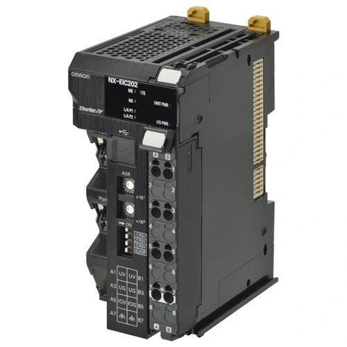
| EtherNet/IP Coupler Unit | 1.60 W or lower | 10 A | NX-EIC202 |
| Item | Specification | |
|---|---|---|
| Enclosure | Mounted in a panel | |
| Grounding method | Ground to 100 Ω or less | |
| Operating environment |
Ambient operating temperature |
0 to 55°C |
| Ambient operating humidity |
10% to 95% (with no condensation or icing) | |
| Atmosphere | Must be free from corrosive gases. | |
| Ambient storage temperature |
-25 to 70°C (with no condensation or icing) | |
| Altitude | 2,000 m max. | |
| Pollution degree | Pollution degree 2 or less: Meets IEC 61010-2-201. | |
| Noise immunity | Conforms to IEC 61000-4-4. 2 kV (power supply line) | |
| Overvoltage category | Category II: Meets IEC 61010-2-201. | |
| EMC immunity level | Zone B | |
| Vibration resistance | Conforms to IEC 60068-2-6. 5 to 8.4 Hz with 3.5-mm amplitude, 8.4 to 150 Hz, acceleration of 9.8 m/s2, 100 min each in X, Y, and Z directions (10 sweeps of 10 min each = 100 min total) *1 |
|
| Shock resistance | Conforms to IEC 60068-2-27. 147 m/s2, 3 times each in X, Y, and Z directions *1 | |
| Applicable standards *2 | cULus: Listed UL508, ANSI/ISA 12.12.01 EU: EN 61131-2, C-Tick or RCM, KC: KC Registration |
|
*1. Refer to the NX-series Digital I/O Units User’s Manual (Cat. No. W521) for the vibration and shock resistance
specifications of the Relay Output Unit.
*2. Consult your OMRON representative for the most recent applicable standards for each model.
| Item | Specification | ||
|---|---|---|---|
| Model | NX-EIC202 | ||
| Number of connectable NX Units |
63 Units max.*1 | ||
| Communications protocols |
EtherNet/IP | ||
| UDP/IP and TCP/IP (Message Services) | Number of buffers (sockets): • 8 message buffers for server • No message buffers for client • Shared buffers for UDP/IP messages and TCP/IP messages Maximum message size: • Request: 492 bytes • Response: 496 bytes Maximum NX output data size: • 490 bytes Maximum NX input data size: • 496 bytes |
||
| Modulation | Baseband | ||
| Link speed | 100 Mbps | ||
| Physical layer | 100BASE-TX (IEEE 802.3) | ||
| Number of connections | 8 | ||
| Received Packet Interval (RPI, refresh cycle) |
4 to 1,000 ms | ||
| Allowed communications bandwidth addressing to the local node |
1,000 pps | ||
| Topology | Line, Tree, Star | ||
| Ethernet Switch | Layer 2 Ethernet switch | ||
| Transmission media | Category 5 or higher twisted-pair cable (Recommended cable: double-shielded cable with aluminum tape and braiding) |
||
| Transmission distance | Distance between nodes: 100 m or less | ||
| NX bus I/O data size | Input: 512 bytes max. (including input data, status, and unused areas) Output: 512 bytes max. (including output data and unused areas) |
||
| EtherNet/IP I/O connection size |
Input: 504 bytes max. (including input data, status, and unused areas) Output: 504 bytes max. (including output data and unused areas) |
||
| Refreshing methods | Free-Run refreshing | ||
| Unit power supply *2 |
Power supply voltage | 24 VDC (20.4 to 28.8 VDC) | |
| NX Unit power supply capacity |
10 W max. (Refer to Installation orientation and restrictions for details.) | ||
| NX Unit power supply efficiency |
70% | ||
| Isolation method | No isolation between NX Unit power supply and Unit power supply terminals | ||
| Current capacity of power supply terminals |
4 A max. | ||
| I/O power supply *2 |
Power supply voltage | 5 to 24 VDC (4.5 to 28.8 VDC) *3 | |
| Maximum I/O power supply current |
10 A (Refer to Installation orientation and restrictions for details.) | ||
| Current capacity of power supply terminals |
10 A max. | ||
| NX Unit power consumption | 1.60 W max. | ||
| Current consumption from I/O power supply |
10 mA max. (for 24 VDC) | ||
| Dielectric strength | 510 VAC for 1 min, leakage current: 5 mA max. (between isolated circuits) | ||
| Insulation resistance | 100 VDC, 20 MΩ min. (between isolated circuits) | ||
| External connection terminals |
Communications Connector For EtherNet/IP communications. • RJ45 × 2 (shielded) |
||
| Screwless Clamping Terminal Block For Unit power supply, I/O power supply, and grounding. Removable. |
|||
| Peripheral USB Port For Sysmac Studio connection. • Physical layer: USB 2.0-compliant, B-type connector • Transmission distance: 5 m max. |
|||
| Dimensions | 46 × 100 × 71 mm (W×H×D) | ||
| Weight | 150 g max. | ||
| Installation orientation and restrictions |
Installation orientation: 6 possible orientations Restrictions: • Used in the upright installation orientation.  • Used in any other orientation than the upright installation orientation.  |
||
| Circuit layout |  |
||
| Terminal arrangement |  |
||
| Accessory | End Cover (NX-END01): 1 | ||
*1. Refer to the NX-series Safety Control Unit User’s Manual (Cat. No. Z930) for the number of Safety Control Units that
can be connected.
*2. Refer to the NX-series EtherNet/IP™Coupler Unit User’s Manual (Cat. No. W536) for procedures for designing the
Unit power supply system and I/O power supply system.
*3. Use a voltage that is appropriate for the I/O circuits of the NX Units and the connected external devices.
Refer to the user’s manuals for information on the NX Units that can be connected to the NX-series EtherNet/IP Coupler Unit.
| Unit | Model |
|---|---|
| EtherNet/IP Coupler Unit | NX-EIC202 |