$ 599.56 – $ 697.06Price range: $ 599.56 through $ 697.06
| Product name |
Specification | Model | ||||
|---|---|---|---|---|---|---|
| Number of channels |
Input/ Output form |
Maximum data length |
Encoder power supply |
Type of external connections |
||
| SSI Input Units |
1 | EIA standard RS-422-A |
32 bits | 24 VDC, 0.3 A/CH |
Screwless push- in terminal block (12 terminals) |
NX-ECS112 |
| 2 | EIA standard RS-422-A |
32 bits | 24 VDC, 0.3 A/CH |
Screwless push- in terminal block (12 terminals) |
NX-ECS212 | |
| Item | Specification | |
|---|---|---|
| Enclosure | Mounted in a panel | |
| Grounding method | Ground to less than 100 Ω | |
| Operating environment |
Ambient operating temperature |
0 to 55°C |
| Ambient operating humidity |
10% to 95% (with no condensation or icing) | |
| Atmosphere | Must be free from corrosive gases. | |
| Ambient storage temperature |
-25 to 70°C (with no condensation or icing) | |
| Altitude | 2,000 m max. | |
| Pollution degree | Pollution degree 2 or less: Meets IEC 61010-2-201. | |
| Noise immunity | Conforms to IEC61000-4-4, 2 kV (power supply line) | |
| Overvoltage category | Category II: Meets IEC 61010-2-201. | |
| EMC immunity level | Zone B | |
| Vibration resistance | Conforms to IEC 60068-2-6. 5 to 8.4 Hz with 3.5-mm amplitude, 8.4 to 150 Hz, acceleration of 9.8 m/s2, 100 min each in X, Y, and Z directions (10 sweeps of 10 min each = 100 min total) |
|
| Shock resistance | Conforms to IEC 60068-2-27. 147 m/s2, 3 times each in X, Y, and Z directions | |
| Applicable standards * | cULus: Listed (UL508) or Listed (UL 61010-2-201),ANSI/ISA 12.12.01, EU: EN 61131-2, C-Tick or RCM, KC Registration, NK, LR |
|
* Ask your OMRON representative for the most recent applicable standards for each model.
| Unit name | SSI Input Unit | Model | NX-ECS112 |
|---|---|---|---|
| Number of channels | 1 channel | Type of external connections |
Screwless push-in terminal block (12 terminals) |
| I/O refreshing method | Free-Run refreshing, synchronous I/O refreshing or task period prioritized refreshing *1 | ||
| Indicators |  |
Input signals | External inputs: 2 Data input (D+, D-) External outputs: 2 Clock output (C+, C-) |
| I/O interface | Synchronized serial interface (SSI) | ||
| Clock output | EIA standard RS-422-A line driver levels | ||
| Data input | EIA standard RS-422-A line receiver levels | ||
| Maximum data length | 32 bits (The single-turn, multi-turn, and status data length can be set.) | ||
| Coding method | No conversion, binary code, or gray code | ||
| Baud Rate | 100 kHz, 200 kHz, 300 kHz, 400 kHz, 500 kHz, 1.0 MHz, 1.5 MHz, or 2.0 MHz | ||
| Dimensions | 12 × 100 × 71 mm (W × H × D) |
Isolation method | Digital isolator |
| Insulation resistance | 20 MΩ min. between isolated circuits (at 100 VDC) |
Dielectric strength |
510 VAC between isolated circuits for 1 minute with leakage current of 5 mA max. |
| I/O power supply source |
Supplied from the NX bus. 20.4 to 28.8 VDC (24 VDC +20%/-15%) |
Current capacity of I/O power supply terminals |
IOV: 0.3 A max. per terminal IOG: 0.3 A max. per terminal |
| NX Unit power consumption |
• Connected to a CPU Unit 1.20 W max. • Connected to a Commu- nications Coupler Unit 0.85 W max. |
Current consumption from I/O power supply |
20mA |
| Maximum transmission distance *2 |
Baud Rate | Maximum transmission distance | |
| 100 kHz | 400m | ||
| 200 kHz | 190m | ||
| 300 kHz | 120m | ||
| 400 kHz | 80m | ||
| 500 kHz | 60m | ||
| 1.0 MHz | 25m | ||
| 1.5 MHz | 10m | ||
| 2.0 MHz | 5m | ||
| Weight | 65g | ||
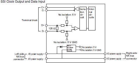
| Circuit layout |  |
||
| Installation orientation and restrictions |
Installation orientation: • Connected to a CPU Unit: Possible in upright installation. • Connected to a Communications Coupler Unit: Possible in 6 orientations. Restrictions: No restrictions |
||
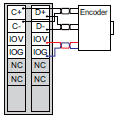
| Terminal connection diagram |
 |
||
| Failure detection | None | Protection | None |
*1. The I/O refreshing method is automatically set according to the connected Communications Coupler Unit and CPU
Unit.
Refer to information on the I/O refreshing methods in the W524 manual for the communications cycles for each
model.
*2. The maximum transmission distance for an SSI Input Unit depends on the baud rate due to the delay that can result
from the responsiveness of the connected encoder and cable impedance. The maximum transmission distance is
only a guideline. Review the specifications for the cables and encoders in the system and evaluate the operation of
the equipment before use.
| Unit name | SSI Input Unit | Model | NX-ECS212 |
|---|---|---|---|
| Number of channels | 2 channels | Type of external connections |
Screwless push-in terminal block (12 terminals) |
| I/O refreshing method | Free-Run refreshing, synchronous I/O refreshing or task period prioritized refreshing *1 | ||
| Indicators |  |
Input signals | External inputs: 2 Data input (D+, D-) External outputs: 2 Clock output (C+, C-) |
| I/O interface | Synchronized serial interface (SSI) | ||
| Clock output | EIA standard RS-422-A line driver levels | ||
| Data input | EIA standard RS-422-A line receiver levels | ||
| Maximum data length | 32 bits (The single-turn, multi-turn, and status data length can be set.) | ||
| Coding method | No conversion, binary code, or gray code | ||
| Baud Rate | 100 kHz, 200 kHz, 300 kHz, 400 kHz, 500 kHz, 1.0 MHz, 1.5 MHz, or 2.0 MHz | ||
| Dimensions | 12 × 100 × 71 mm (W × H × D) |
Isolation method | Digital isolator |
| Insulation resistance | 20 MΩ min. between isolated circuits (at 100 VDC) |
Dielectric strength |
510 VAC between isolated circuits for 1 minute with leakage current of 5 mA max. |
| I/O power supply source |
Supplied from the NX bus. 20.4 to 28.8 VDC (24 VDC +20%/-15%) |
Current capacity of I/O power supply terminals |
IOV: 0.3 A max. per terminal IOG: 0.3 A max. per terminal |
| NX Unit power consumption |
• Connected to a CPU Unit 1.25 W max. • Connected to a Commu- nications Coupler Unit 0.9 W max. |
Current consumption from I/O power supply |
30mA |
| Maximum transmission distance *2 |
Baud Rate | Maximum transmission distance | |
| 100 kHz | 400m | ||
| 200 kHz | 190m | ||
| 300 kHz | 120m | ||
| 400 kHz | 80m | ||
| 500 kHz | 60m | ||
| 1.0 MHz | 25m | ||
| 1.5 MHz | 10m | ||
| 2.0 MHz | 5m | ||
| Weight | 65g | ||
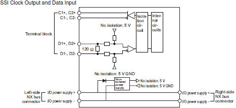
| Circuit layout |  |
||
| Installation orientation and restrictions |
Installation orientation: • Connected to a CPU Unit: Possible in upright installation. • Connected to a Communications Coupler Unit: Possible in 6 orientations. Restrictions: No restrictions |
||
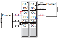
| Terminal connection diagram |
 |
||
| Failure detection | None | Protection | None |
*1. The I/O refreshing method is automatically set according to the connected Communications Coupler Unit and CPU
Unit.
Refer to information on the I/O refreshing methods in the W524 manual for the communications cycles for each
model.
*2. The maximum transmission distance for an SSI Input Unit depends on the baud rate due to the delay that can result
from the responsiveness of the connected encoder and cable impedance. The maximum transmission distance is
only a guideline. Review the specifications for the cables and encoders in the system and evaluate the operation of
the equipment before use.