*Ask your OMRON representative for the most recent applicable standards for each model.
$ 301.60 – $ 365.82Price range: $ 301.60 through $ 365.82
| Product name |
Specification | Model | |||||
|---|---|---|---|---|---|---|---|
| Number of channels |
External inputs |
Maximum response frequency |
I/O refreshing method * |
Number of I/O entry mappings |
Remarks | ||
| Incremental Encoder Input Unit |
1 (NPN) |
3 (NPN) |
500 kHz | • Free-Run refreshing • Synchro- nous I/O refreshing • Task period prioritized refreshing |
1/1 | 24-V voltage input |
NX-EC0112 |
| 1 (PNP) |
3 (PNP) |
NX-EC0122 | |||||
| 1 | 3 (NPN) |
4 MHz | Line receiver input |
NX-EC0132 | |||
| 3 (PNP) |
NX-EC0142 | ||||||
| 2 (NPN) |
None | 500 kHz | 2/2 | 24-V voltage input |
NX-EC0212 | ||
| 2 (PNP) |
NX-EC0222 | ||||||
* Refer to the I/O Refreshing Methods in the USER’S MANUAL (Cat. No. W524) for the communications cycles for each
model.
| Item | Specification | |
|---|---|---|
| Enclosure | Mounted in a panel | |
| Grounding method | Ground to less than 100 Ω | |
| Operating environment |
Ambient operating temperature | 0 to 55°C |
| Ambient operating humidity | 10% to 95% (with no condensation or icing) | |
| Atmosphere | Must be free from corrosive gases. | |
| Ambient storage temperature | -25 to 70°C (with no condensation or icing) | |
| Altitude | 2,000 m max. | |
| Pollution degree | Pollution degree 2 or less: Meets IEC 61010-2-201. | |
| Noise immunity | Conforms to IEC61000-4-4, 2 kV (power supply line) | |
| Overvoltage category | Category II: Meets IEC 61010-2-201. | |
| EMC immunity level | Zone B | |
| Vibration resistance | Conforms to IEC 60068-2-6. 5 to 8.4 Hz with 3.5-mm amplitude, 8.4 to 150 Hz, acceleration of 9.8 m/s2, 100 min each in X, Y, and Z directions (10 sweeps of 10 min each = 100 min total) |
|
| Shock resistance | Conforms to IEC 60068-2-27. 147 m/s2, 3 times each in X, Y, and Z directions |
|
| Applicable standards * | cULus: Listed (UL508) or Listed (UL 61010-2-201), ANSI/ISA 12.12.01, EU: EN 61131-2, C-Tick or RCM, KC Registration, NK, LR |
|
*Ask your OMRON representative for the most recent applicable standards for each model.
| Unit name | Incremental Encoder Input Unit | Model | NX-EC0112 | |
|---|---|---|---|---|
| Number of channels | 1 channel | Type of external connections |
Screwless clamping terminal block (16 terminals) |
|
| I/O refreshing method | Free-Run refreshing, synchronous I/O refreshing or task period prioritized refreshing * | |||
| Indicators |  |
Input signals | Counter: Phases A, B, and Z External Inputs: 3 |
|
| Input form | Voltage input (24 V) | |||
| Counting unit | Pulses | |||
| Pulse input method | Phase differential pulse (multiplication x2/4), pulse + direction inputs, or up and down pulse inputs |
|||
| Counter range | -2,147,483,648 to 2,147,483,647 pulses | |||
| Counter functions | ||||
| Counter type | Ring counter or linear counter | |||
| Counter controls | Gate control, counter reset, and counter preset | |||
| Latch function | Two external input latches and one internal latch | |||
| Measurements | Two external input latches and one internal latch | |||
| Voltage input specifications | ||||
| Input voltage | 20.4 to 28.8 VDC (24 VDC +20%/-15%) |
ON voltage | 19.6 VDC min./3 mA min. | |
| Input current | 4.2 mA typical (24 VDC) | OFF voltage | 4.0 VDC max./1 mA max. | |
| Maximum response frequency |
Phases A and B: Single-phase 500 kHz (phase differential pulse input x4: 125 kHz), Phase Z: 125 kHz |
|||
| Internal I/O common processing |
NPN | |||
| External input specifications | ||||
| Input voltage | 20.4 to 28.8 VDC (24 VDC +20%, -15%) |
ON voltage/ ON current |
15 VDC min./3 mA min. | |
| Input current | 4.6 mA typical (24 VDC) | OFF voltage/ OFF current |
4.0 VDC max./1 mA max. | |
| ON/OFF response time |
1 μs max./2 μs max. | |||
| Internal I/O common processing |
NPN | |||
| Dimensions | 12 × 100 × 71 mm (W × H × D) |
Isolation method | Photocoupler isolation | |
| Insulation resistance | 20 MΩ min. between isolated circuits (at 100 VDC) |
Dielectric strength |
510 VAC between isolated circuits for 1 minute with leakage current of 5 mA max. |
|
| I/O power supply method |
Supplied from the NX bus. 20.4 to 28.8 VDC (24 VDC +20%, -15%) |
Current capacity of I/O power supply terminals |
IOV: 0.3 A max. per terminal for encoder supply section and 0.1 A max. per terminal for other sections IOG: 0.3 A max. per terminal for encoder supply section and 0.1 A max. per terminal for other sections |
|
| NX Unit power consumption |
• Connected to a CPU Unit 1.15 W max. • Connected to a Commu- nications Coupler Unit 0.85 W max. |
Current consumption from I/O power supply |
None | |
| Weight | 70 g max. | |||
| Circuit layout | 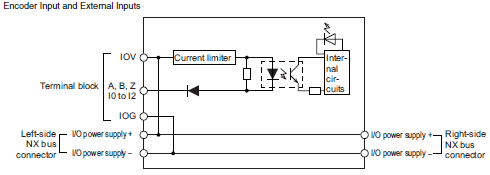 |
|||
| Installation orientation and restrictions |
Installation orientation: • Connected to a CPU Unit: Possible in upright installation. • Connected to a Communications Coupler Unit: Possible in 6 orientations. Restrictions: There are no restrictions. |
|||
| Terminal connection diagram |
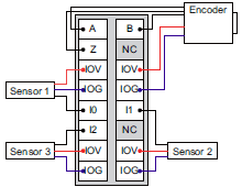 |
|||
| Failure detection | None | Protection | None | |
* The I/O refreshing method is automatically set according to the connected Communications Coupler Unit and CPU Unit.
| Unit name | Incremental Encoder Input Unit | Model | NX-EC0122 | |
|---|---|---|---|---|
| Number of channels | 1 channel | Type of external connections |
Screwless push-in terminal block (16 terminals) |
|
| I/O refreshing method | Free-Run refreshing, synchronous I/O refreshing or task period prioritized refreshing * | |||
| Indicators |  |
Input signals | Counter: Phases A, B, and Z External Inputs: 3 |
|
| Input form | Voltage input (24 V) | |||
| Counting unit | Pulses | |||
| Pulse input method | Phase difference pulse (multiplication x2/4), pulse + direction inputs, or up and down pulse inputs |
|||
| Counter range | -2,147,483,648 to 2,147,483,647 pulses | |||
| Counter functions | ||||
| Counter type | Ring counter or linear counter | |||
| Counter controls | Gate control, counter reset, and counter preset | |||
| Latch function | Two external input latches and one internal latch | |||
| Measurements | Two external input latches and one internal latch | |||
| Voltage input specifications | ||||
| Input voltage | 20.4 to 28.8 VDC (24 VDC +20%/-15%) |
ON voltage | 19.6 VDC min./3 mA min. | |
| Input current | 4.2 mA typical (24 VDC) | OFF voltage | 4.0 VDC max./1 mA max. | |
| Maximum response frequency |
Phases A and B: Single-phase 500 kHz (phase difference pulse input x4: 125 kHz), Phase Z: 125 kHz |
|||
| Internal I/O common processing |
PNP | |||
| External input specifications | ||||
| Input voltage | 20.4 to 28.8 VDC (24 VDC +20%/-15%) |
ON voltage/ ON current |
15 VDC min./3 mA min. | |
| Input current | 4.6 mA typical (24 VDC) | OFF voltage/ OFF current |
4.0 VDC max./1 mA max. | |
| ON/OFF response time |
1 μs max./2 μs max. | |||
| Internal I/O common processing |
PNP | |||
| Dimensions | 12 × 100 × 71 mm (W × H × D) |
Isolation method | Photocoupler isolation | |
| Insulation resistance | 20 MΩ min. between isolated circuits (at 100 VDC) |
Dielectric strength |
510 VAC between isolated circuits for 1 minute with leakage current of 5 mA max. |
|
| I/O power supply source |
Supplied from the NX bus. 20.4 to 28.8 VDC (24 VDC +20%/-15%) |
Current capacity of I/O power supply terminals |
IOV: 0.3 A max. per terminal for encoder supply section and 0.1 A max. per terminal for other sections IOG: 0.3 A max. per terminal for encoder supply section and 0.1 A max. per terminal for other sections |
|
| NX Unit power consumption |
• Connected to a CPU Unit 1.30 W max. • Connected to a Commu- nications Coupler Unit 0.95 W max. |
Current consumption from I/O power supply |
None | |
| Weight | 70 g max. | |||
| Circuit layout | 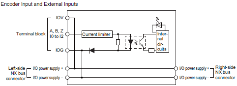 |
|||
| Installation orientation and restrictions |
Installation orientation: • Connected to a CPU Unit: Possible in upright installation. • Connected to a Communications Coupler Unit: Possible in 6 orientations. Restrictions: There are no restrictions. |
|||
| Terminal connection diagram |
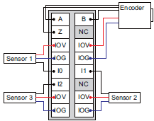 |
|||
| Failure detection | None | Protection | None | |
* The I/O refreshing method is automatically set according to the connected Communications Coupler Unit and CPU Unit.
| Unit name | Incremental Encoder Input Unit | Model | NX-EC0132 | |
|---|---|---|---|---|
| Number of channels | 1 channel | Type of external connections |
Screwless clamping terminal block (12 terminals × 2) |
|
| I/O refreshing method | Free-Run refreshing, synchronous I/O refreshing or task period prioritized refreshing * | |||
| Indicators |  |
Input signals | Counter: Phases A, B, and Z External Inputs: 3 |
|
| Input form | Line receiver input | |||
| Counting unit | Pulses | |||
| Pulse input method | Phase differential pulse (multiplication x2/4), pulse + direction inputs, or up and down pulse inputs |
|||
| Counter range | -2,147,483,648 to 2,147,483,647 pulses | |||
| Counter functions | ||||
| Counter type | Ring counter or linear counter | |||
| Counter controls | Gate control, counter reset, and counter preset | |||
| Latch function | Two external input latches and one internal latch | |||
| Measurements | Pulse rate measurement and pulse period measurement | |||
| Line driver specifications | ||||
| Input voltage | EIA standard RS-422-A line driver levels |
High level input voltage |
VIT+: 0.1 V min. | |
| Input impedance | 120 Ω ± 5% | Low level input voltage |
VIT-: -0.1 V min. | |
| Hysteresis voltage | Vhys (VIT+ – VIT-): 60 mV | |||
| Maximum response frequency |
Phases A and B: Single-phase 4 MHz (phase differential pulse input x4: 1 MHz), Phase Z: 1 MHz |
|||
| 5-V power supply for encoder |
Output voltage: 5 VDC ±5% Output current: 500 mA max. |
|||
| External input specifications | ||||
| Input voltage | 20.4 to 28.8 VDC (24 VDC +20%, -15%) |
ON voltage/ ON current |
15 VDC min./3 mA min. | |
| Input current | 3.5 mA typical (24 VDC) | OFF voltage/ OFF current |
5.0 VDC max./1 mA max. | |
| ON/OFF response time |
1 μs max./1 μs max. | |||
| Internal I/O common processing |
NPN | |||
| Dimensions | 12 × 100 × 71 mm (W × H × D) |
Isolation method | Digital isolator | |
| Insulation resistance | 20 MΩ min. between isolated circuits (at 100 VDC) |
Dielectric strength |
510 VAC between isolated circuits for 1 minute with leakage current of 5 mA max. |
|
| I/O power supply method |
Supplied from the NX bus. 20.4 to 28.8 VDC (24 VDC +20%, -15%) |
Current capacity of I/O power supply terminals |
IOV: 0.1 A max. per terminal IOG: 0.1 A max. per terminal |
|
| NX Unit power consumption |
• Connected to a CPU Unit 1.25 W max. • Connected to a Commu- nications Coupler Unit 0.95 W max. |
Current consumption from I/O power supply |
Unit current consumption: 30 mA max. Consumption from encoder 5-V power supply: 0.28 × Encoder current consumption mA |
|
| Weight | 130 g max. | |||
| Circuit layout | 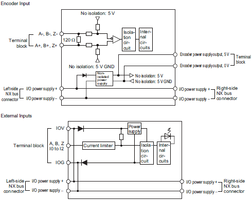 |
|||
| Installation orientation and restrictions |
Installation orientation: • Connected to a CPU Unit: Possible in upright installation. • Connected to a Communications Coupler Unit: Possible in 6 orientations. Restrictions: There are no restrictions. |
|||
| Terminal connection diagram |
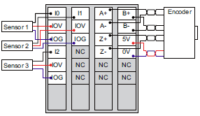 |
|||
| Failure detection | None | Protection | None | |
* The I/O refreshing method is automatically set according to the connected Communications Coupler Unit and CPU Unit.
| Unit name | Incremental Encoder Input Unit | Model | NX-EC0142 | |
|---|---|---|---|---|
| Number of channels | 1 channel | Type of external connections |
Screwless push-in terminal block (12 terminals × 2) |
|
| I/O refreshing method | Free-Run refreshing, synchronous I/O refreshing or task period prioritized refreshing * | |||
| Indicators |  |
Input signals | Counter: Phases A, B, and Z External Inputs: 3 |
|
| Input form | Line receiver input | |||
| Counting unit | Pulses | |||
| Pulse input method | Phase difference pulse (multiplication x2/4), pulse + direction inputs, or up and down pulse inputs |
|||
| Counter range | -2,147,483,648 to 2,147,483,647 pulses | |||
| Counter functions | ||||
| Counter type | Ring counter or linear counter | |||
| Counter controls | Gate control, counter reset, and counter preset | |||
| Latch function | Two external input latches and one internal latch | |||
| Measurements | Pulse rate measurement and pulse period measurement | |||
| Line driver specifications | ||||
| Input voltage | EIA standard RS-422-A line driver levels |
High level input voltage |
VIT+: 0.1 V min. | |
| Input impedance | 120 Ω ± 5% | Low level input voltage |
VIT-: -0.1 V min. | |
| Hysteresis voltage | Vhys (VIT+ – VIT-): 60 Mv | |||
| Maximum response frequency |
Phases A and B: Single-phase 4 MHz (phase difference pulse input x4: 1 MHz), Phase Z: 1 MHz |
|||
| 5-V power supply for encoder |
Output voltage: 5 VDC Output current: 500 mA max. |
|||
| External input specifications | ||||
| Input voltage | 20.4 to 28.8 VDC (24 VDC +20%/.15%) |
ON voltage/ ON current |
15 VDC min./3 mA min. | |
| Input current | 3.5 mA typical (24 VDC) | OFF voltage/ OFF current |
4.0 VDC max./1 mA max. | |
| ON/OFF response time |
1 μs max./2 μs max. | |||
| Internal I/O common processing |
PNP | |||
| Dimensions | 12 × 100 × 71 mm (W × H × D) |
Isolation method | Photocoupler isolation | |
| Insulation resistance | 20 MΩ min. between isolated circuits (at 100 VDC) |
Dielectric strength |
510 VAC between isolated circuits for 1 minute with leakage current of 5 mA max. |
|
| I/O power supply source |
Supplied from the NX bus. 20.4 to 28.8 VDC (24 VDC +20%/-15%) |
Current capacity of I/O power supply terminals |
IOV: 0.1 A max. per terminal IOG: 0.1 A max. per terminal |
|
| NX Unit power consumption |
• Connected to a CPU Unit 1.50 W max. • Connected to a Commu- nications Coupler Unit 1.05 W max. |
Current consumption from I/O power supply |
Unit current consumption: 30 mA max. Consumption from encoder 5-V power supply: 0.28 × Encoder current consumption mA |
|
| Weight | 130 g max. | |||
| Circuit layout |  |
|||
| Installation orientation and restrictions |
Installation orientation: • Connected to a CPU Unit: Possible in upright installation. • Connected to a Communications Coupler Unit: Possible in 6 orientations. Restrictions: There are no restrictions. |
|||
| Terminal connection diagram |
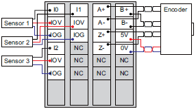 |
|||
| Failure detection | None | Protection | None | |
* The I/O refreshing method is automatically set according to the connected Communications Coupler Unit and CPU Unit.
| Unit name | Incremental Encoder Input Unit | Model | NX-EC0212 | |
|---|---|---|---|---|
| Number of channels | 2 channels | Type of external connections |
Screwless clamping terminal block (12 terminals) |
|
| I/O refreshing method | Free-Run refreshing, synchronous I/O refreshing or task period prioritized refreshing * | |||
| Indicators |  |
Input signals | Counter: Phases A, B, and Z External Inputs: None |
|
| Input form | Voltage input (24 V) | |||
| Counting unit | Pulses | |||
| Pulse input method | Phase differential pulse (multiplication x2/4), pulse + direction inputs, or up and down pulse inputs |
|||
| Counter range | -2,147,483,648 to 2,147,483,647 pulses | |||
| Counter functions | ||||
| Counter type | Ring counter or linear counter | |||
| Counter controls | Gate control, counter reset, and counter preset | |||
| Latch function | Two external input latches and one internal latch | |||
| Measurements | Two external input latches and one internal latch | |||
| Voltage input specifications | ||||
| Input voltage | 20.4 to 28.8 VDC (24 VDC +20%, -15%) |
ON voltage | 19.6 VDC min./3 mA min. | |
| Input current | 4.2 mA typical (24 VDC) | OFF voltage | 4.0 VDC max./1 mA max. | |
| Maximum response frequency |
Phases A and B: Single-phase 500 kHz (phase differential pulse input x4: 125 kHz), Phase Z: 125 kHz |
|||
| Internal I/O common processing |
NPN | |||
| External input specifications | ||||
| Input voltage | – | ON voltage/ ON current |
– | |
| Input current | – | OFF voltage/ OFF current |
– | |
| ON/OFF response time | – | |||
| Internal I/O common processing |
– | |||
| Dimensions | 12 × 100 × 71 mm (W × H × D) |
Isolation method | Photocoupler isolation | |
| Insulation resistance | 20 MΩ min. between isolated circuits (at 100 VDC) |
Dielectric strength |
510 VAC between isolated circuits for 1 minute with leakage current of 5 mA max. |
|
| I/O power supply method |
Supplied from the NX bus. 20.4 to 28.8 VDC (24 VDC +20%, -15%) |
Current capacity of I/O power supply terminals |
IOV: 0.3 A max. per terminal IOG: 0.3 A max. per terminal |
|
| NX Unit power consumption |
• Connected to a CPU Unit 1.15 W max. • Connected to a Commu- nications Coupler Unit 0.85 W max. |
Current consumption from I/O power supply |
None | |
| Weight | 70 g max. | |||
| Circuit layout | 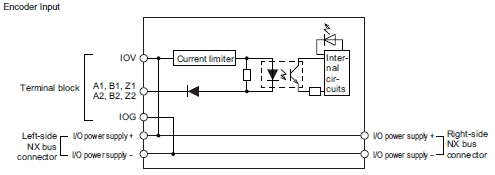 |
|||
| Installation orientation and restrictions |
Installation orientation: • Connected to a CPU Unit: Possible in upright installation. • Connected to a Communications Coupler Unit: Possible in 6 orientations. Restrictions: There are no restrictions. |
|||
| Terminal connection diagram |
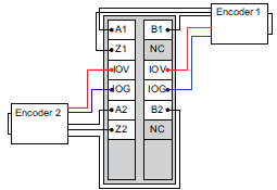 |
|||
| Failure detection | None | Protection | None | |
* The I/O refreshing method is automatically set according to the connected Communications Coupler Unit and CPU Unit.
| Unit name | Incremental Encoder Input Unit | Model | NX-EC0222 | |
|---|---|---|---|---|
| Number of channels | 2 channels | Type of external connections |
Screwless push-in terminal block (12 terminals) |
|
| I/O refreshing method | Free-Run refreshing, synchronous I/O refreshing or task period prioritized refreshing * | |||
| Indicators |  |
Input signals | Counter: Phases A, B, and Z External Inputs: None |
|
| Input form | Voltage input (24 V) | |||
| Counting unit | Pulses | |||
| Pulse input method | Phase difference pulse (multiplication x2/4), pulse + direction inputs, or up and down pulse 3inputs |
|||
| Counter range | -2,147,483,648 to 2,147,483,647 pulses | |||
| Counter functions | ||||
| Counter type | Ring counter or linear counter | |||
| Counter controls | Gate control, counter reset, and counter preset | |||
| Latch function | Two external input latches and one internal latch | |||
| Measurements | Two external input latches and one internal latch | |||
| Voltage input specifications | ||||
| Input voltage | 20.4 to 28.8 VDC (24 VDC +20%/-15%) |
ON voltage | 19.6 VDC min./3 mA min. | |
| Input current | 4.2 mA typical (24 VDC) | OFF voltage | 4.0 VDC max./1 mA max. | |
| Maximum response frequency |
Phases A and B: Single-phase 500 kHz (phase difference pulse input x4: 125 kHz), Phase Z: 125 kHz |
|||
| Internal I/O common processing |
PNP | |||
| External input specifications | ||||
| Input voltage | – | ON voltage/ ON current |
– | |
| Input current | – | OFF voltage/ OFF current |
– | |
| ON/OFF response time |
– | |||
| Internal I/O common processing |
– | |||
| Dimensions | 12 × 100 × 71 mm (W × H × D) |
Isolation method | Photocoupler isolation | |
| Insulation resistance | 20 MΩ min. between isolated circuits (at 100 VDC) |
Dielectric strength |
510 VAC between isolated circuits for 1 minute with leakage current of 5 mA max. |
|
| I/O power supply source |
Supplied from the NX bus. 20.4 to 28.8 VDC (24 VDC +20%/-15%) |
Current capacity of I/O power supply terminals |
IOV: 0.3 A max. per terminal IOG: 0.3 A max. per terminal |
|
| NX Unit power consumption |
• Connected to a CPU Unit 1.30 W max. • Connected to a Commu- nications Coupler Unit 0.95 W max. |
Current consumption from I/O power supply |
None | |
| Weight | 70 g max. | |||
| Circuit layout | 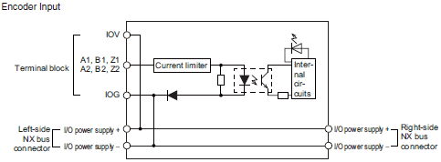 |
|||
| Installation orientation and restrictions |
Installation orientation: • Connected to a CPU Unit: Possible in upright installation. • Connected to a Communications Coupler Unit: Possible in 6 orientations. Restrictions: There are no restrictions. |
|||
| Terminal connection diagram |
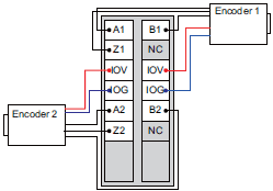 |
|||
| Failure detection | None | Protection | None | |
* The I/O refreshing method is automatically set according to the connected Communications Coupler Unit and CPU Unit.