| Operating modes | Supply voltage | Control output | H3DT-F | |
|---|---|---|---|---|
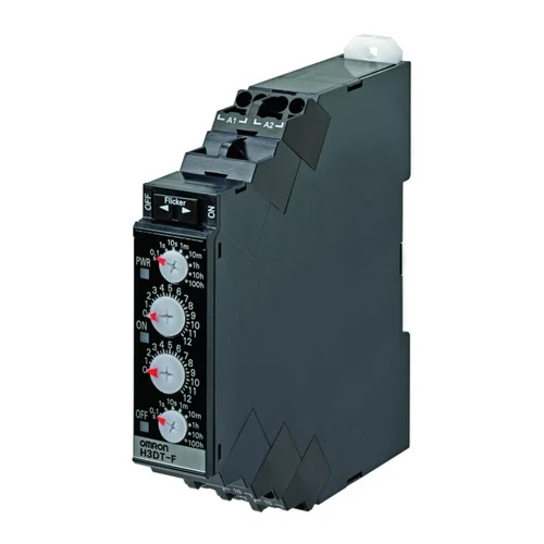
| Flicker OFF start/flicker ON start | 24 to 240 VAC/DC | Contact output: SPDT | Model | H3DT-F |
| Model | Operating modes | Terminal block | Output type | Mounting method | Safety standards |
|---|---|---|---|---|---|
| H3DT-F | Flicker OFF start/flicker ON start |
6 terminals | Relay, SPDT | DIN Track mounting | cULus (UL508 CSA C22.2 No. 14) CCC LR EN 61812-1 IEC 60664-1 4 kV/2 |
| Time range setting | 0.1 s | 1 s | 10 s | 1 min | 10 min | 1 h | 10 h | 100 h |
|---|---|---|---|---|---|---|---|---|
| Set time range | 0.1 to 1.2 s | 1 to 12 s | 10 to 120 s | 1 to 12 min | 10 to 120 min |
1 to 12 h | 10 to 120 h | 100 to 1,200 h |
| Scale numbers | 12 | |||||||
| Power supply voltage *1 | 24 to 240 VAC/DC, 50/60 Hz *2 | |
|---|---|---|
| Allowable voltage fluctuation range | 85% to 110% of rated voltage | |
| Power reset | Minimum power-OFF time: 0.1 s | |
| Reset voltage | 10% of rated voltage | |
| Power consumption | H3DT-F | At 240 VAC: 1.9VA max., at 240 VDC: 0.6W max., at 24 VDC: 0.3W max. |
| Rated Insulation Voltage | 250 VAC | |
| Control output | Contact output: 5 A at 250 VAC with resistive load (cosφ = 1), 5 A at 30 VDC with resistive load, 0.15 A max. at 125 VDC with resistive load, 0.1 A max. at 125 VDC with L/R of 7 ms. The minimum applicable load is 10 mA at 5 VDC (P reference value). Contact materials: Ag-alloy (Recommended fuse: BLN5 (Littelfuse) or 0216005MXEP) |
|
| Ambient operating temperature | -20 to 60°C (with no icing) | |
| Storage temperature | -40 to 70°C (with no icing) | |
| Surrounding air operating humidity |
25% to 85% | |
*1. When using a 24-VDC power supply voltage, there will be an inrush current of approximately 0.5 A.
Allow for this inrush current when turning ON and OFF the power supply to the Timer with device with a solid-state output,
such as a sensor.
*2. DC ripple: 20% max.
| Accuracy of operating time | ±1% of FS max. (±1% ±10 ms max. at 1.2-s range) | |
|---|---|---|
| Setting error | ±10% of FS ±0.05 s max. | |
| Influence of voltage | ±0.5% of FS max. (±0.5% ±10 ms max. at 1.2-s range) | |
| Influence of temperature | ±2% of FS max. (±2% ±10 ms max. at 1.2-s range) | |
| Insulation resistance | 100 MΩ min. at 500 VDC | |
| Dielectric strength | Between charged metal part and operating section: 2,900 VAC 50/60 Hz for 1 min. Between control output terminals and operating circuit: 2,000 VAC 50/60 Hz for 1 min. Between contacts not located next to each other: 1,000 VAC 50/60 Hz for 1 min. |
|
| Impulse withstand test voltage | 5 kV between power terminals, 7.4 kV between conductor terminal and operating section |
|
| Noise immunity | Square-wave noise generated by noise simulator (pulse width: 100 ns/1 μs, 1-ns rise): ±1.5 kV |
|
| Static immunity | Malfunction: 4 kV, Destruction: 8 kV | |
| Vibration resistance |
Destruction | 0.75-mm single amplitude at 10 to 55 Hz for 2 h each in 3 directions |
| Malfunction | 0.5-mm single amplitude at 10 to 55 Hz for 10 min each in 3 directions | |
| Shock resistance |
Destruction | 1,000 m/s2 3 times each in 6 directions |
| Malfunction | 100 m/s2 3 times each in 6 directions | |
| Life expectancy |
Mechanical | 10 million operations min. (under no load at 1,800 operations/h) |
| Electrical | 100,000 operations min. (5 A at 250 VAC, resistive load at 360 operations/h) | |
| Degree of protection | IP30 (Terminal block: IP20) | |
| Weight | Approx. 90 g | |