| Operating modes | Supply voltage | Control output | H3DK-F | |
|---|---|---|---|---|
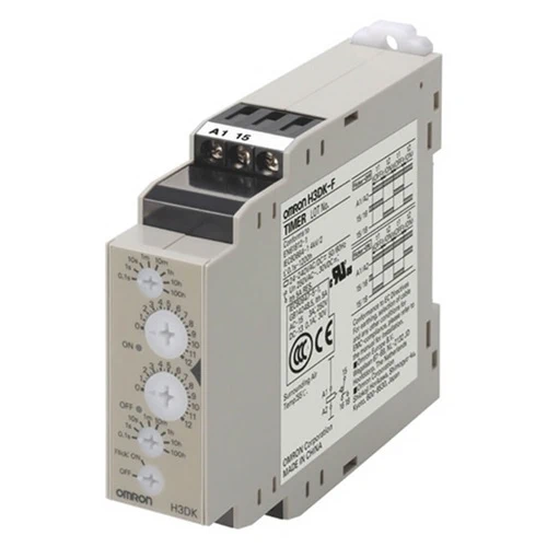
| Flicker OFF start/ flicker ON start |
24 to 240 VAC/DC | Contact output: SPDT | Model | H3DK-F |
| 12 VDC | Contact output: SPDT | Model | H3DK-FA | |
| Time range setting |
0.1 s | 1 s | 10 s | 1 min | 10 min | 1 h | 10 h | 100 h |
|---|---|---|---|---|---|---|---|---|
| Set time range |
0.1 to 1.2 s | 1 to 12 s | 10 to 120 s | 1 to 12 min | 10 to 120 min | 1 to 12 h | 10 to 120 h | 100 to 1,200 h |
| Scale numbers |
12 | |||||||
Note: When the main dial is set to “0” for all settings, the output will operate instantaneously.
| Power supply voltage *1 | 24 to 240 VAC/DC, 50/60 Hz *2 12 VDC *2 |
|
|---|---|---|
| Allowable voltage fluctuation range |
24 to 240 VAC/DC: 85% to 110% of rated voltage 12 VDC: 90% to 110% of rated voltage |
|
| Power reset | Minimum power-OFF time: 0.1 s | |
| Reset voltage | 10% of rated voltage | |
| Power consumption |
H3DK-F | At 240 VAC: 4.5VA max. *3 |
| H3DK-FA | At 12 VDC: 0.6 W max. | |
| Control output | Contact output: 5 A at 250 VAC with resistive load (cosφ = 1), 5 A at 30 VDC with resistive load *4, 0.15 A max. at 125 VDC with resistive load, 0.1 A at 125 VDC with L/R of 7 ms. The minimum applicable load is 10 mA at 5 VDC (P reference value). Contact materials: Ag-alloy + Gold plating |
|
| Ambient operating temperature | -20 to 55°C (with no icing) | |
| Storage temperature | -40 to 70°C (with no icing) | |
| Ambient operating humidity | 25% to 85% | |
*1. When using a 24-VDC power supply voltage, there will be an inrush current of approximately 0.25 A. Allow for this
inrush current when turning ON and OFF the power supply to the Timer with device with a solid-state output, such
as a sensor.
*2. DC ripple: 20% max.
*3. Refer to DC Power Consumptions (Reference Information) on Catalog for DC power consumptions.
*4. The control output ratings are for one H3DK operating alone. If you operate two or more Timers side by side, refer
to Installation Pitch and Output Switching Capacity (Reference Values) on the Catalog.
| Accuracy of operating time |
±1% of FS max. (±1% ±10 ms max. at 1.2-s range) | |
|---|---|---|
| Setting error | ±10% of FS ±0.05 s max. | |
| Influence of voltage | ±0.5% of FS max. (±0.5% ±10 ms max. at 1.2-s range) | |
| Influence of temperature | ±2% of FS max. (±2% ±10 ms max. at 1.2-s range) | |
| Insulation resistance | 100 MΩ min. at 500 VDC | |
| Dielectric strength | Between current-carrying metal parts and exposed non-current-carrying metal parts: 2,000 VAC 50/60 Hz for 1 min. Between control output terminals and operating circuit: 2,000 VAC 50/60 Hz for 1 min. Between contacts not located next to each other: 1,000 VAC 50/60 Hz for 1 min. |
|
| Impulse withstand voltage | 24 to 240 VAC/VDC: 5 kV between power terminals, 5 kV between current-carrying metal parts and exposed non-current-carrying metal parts 12 VDC: 1 kV between power terminals, 1.5 kV between current-carrying metal parts and exposed non-current-carrying metal parts |
|
| Noise immunity | Square-wave noise generated by noise simulator (pulse width: 100 ns/1 μs, 1-ns rise): ±1.5 kV |
|
| Static immunity | Malfunction: 4 kV, Destruction: 8 kV | |
| Vibration resistance |
Destruction | 0.75-mm single amplitude at 10 to 55 Hz for 2 h each in 3 directions |
| Malfunction | 0.5-mm single amplitude at 10 to 55 Hz for 10 min each in 3 directions | |
| Shock resistance |
Destruction | 1,000 m/s2 3 times each in 6 directions |
| Malfunction | 100 m/s2 3 times each in 6 directions | |
| Life expectancy |
Mechanical | 10 million operations min. (under no load at 1,800 operations/h) |
| Electrical | 100,000 operations min. (5 A at 250 VAC, resistive load at 360 operations/h) | |
| Degree of protection | IP30 (Terminal block: IP20) | |
| Weight | Approx. 110 g | |