Omron produce industrial sensors range such as fiber sensors, photoelectric sensors, displacement sensors/ measurement sensors, proximity sensors, photomicro sensors and rotary encodes.
Lineup
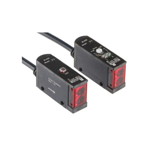
Built-in Amplifier Photoelectric Sensors
| Sensing method |
Connection method |
Sensing distance |
Functions | Model | |
|---|---|---|---|---|---|
| NPN output | PNP output | ||||
| Through- beam Sensors *1 |
Pre-wired | 7 m (Red light) |
— | E3S-AT11 2M Emitter E3S-AT11-L Receiver E3S-AT11-D |
E3S-AT31 2M Emitter E3S-AT31-L Receiver E3S-AT31-D |
 |
E3S-AT21 2M Emitter E3S-AT21-L Receiver E3S-AT21-D |
E3S-AT41 2M Emitter E3S-AT41-L Receiver E3S-AT41-D |
|||
| Connector (M12) |
— | E3S-AT16 Emitter E3S-AT16-L Receiver E3S-AT16-D |
E3S-AT36 Emitter E3S-AT36-L Receiver E3S-AT36-D |
||
| Pre-wired | — | E3S-AT61 2M Emitter E3S-AT61-L Receiver E3S-AT61-D |
E3S-AT81 2M Emitter E3S-AT81-L Receiver E3S-AT81-D |
||
|
E3S-AT71 2M Emitter E3S-AT71-L Receiver E3S-AT71-D |
E3S-AT91 2M Emitter E3S-AT91-L Receiver E3S-AT91-D |
|||
| Connector (M12) |
— | E3S-AT66 Emitter E3S-AT66-L Receiver E3S-AT66-D |
E3S-AT86 Emitter E3S-AT86-L Receiver E3S-AT86-D |
||
| Retro- reflective Sensors |
Pre-wired | 2 m (100 mm) *2 (Red light) |
— | E3S-AR11 2M | E3S-AR31 2M |
|
E3S-AR21 2M | E3S-AR41 2M | |||
| Connector (M12) |
— | E3S-AR16 | E3S-AR36 | ||
| Pre-wired | — | E3S-AR61 2M | E3S-AR81 2M | ||
|
E3S-AR71 2M | E3S-AR91 2M | |||
| Connector (M12) |
— | E3S-AR66 | E3S-AR86 | ||
| Diffuse- reflective Sensors |
Pre-wired | 100 mm (wide view) (Infrared light) |
— | E3S-AD13 2M | E3S-AD33 2M |
 |
E3S-AD23 2M | E3S-AD43 2M | |||
| 200 mm (Red light) |
— | E3S-AD11 2M | E3S-AD31 2M | ||
 |
E3S-AD21 2M | E3S-AD41 2M | |||
| 700 mm (Infrared light) |
— | E3S-AD12 2M | E3S-AD32 2M | ||
|
E3S-AD22 2M | E3S-AD42 2M | |||
| Connector (M12) |
100 mm (wide view) (Infrared light) |
— | E3S-AD18 | E3S-AD38 | |
| 200 mm (Red light) |
E3S-AD16 | E3S-AD36 | |||
| 700 mm (Infrared light) |
E3S-AD17 | E3S-AD37 | |||
| Pre-wired | 100 mm (wide view) (Infrared light) |
— | E3S-AD63 2M | E3S-AD83 2M | |
|
E3S-AD73 2M | E3S-AD93 2M | |||
| 200 mm (Red light) |
— | E3S-AD61 2M | E3S-AD81 2M | ||
|
E3S-AD71 2M | E3S-AD91 2M | |||
| 700 mm (Infrared light) |
— | E3S-AD62 2M | E3S-AD82 2M | ||
|
E3S-AD72 2M | E3S-AD92 2M | |||
| Connector (M12) |
100 mm (wide view) (Infrared light) |
— | E3S-AD68 | E3S-AD88 | |
| 200 mm (Red light) |
E3S-AD66 | E3S-AD86 | |||
| 700 mm (Infrared light) |
E3S-AD67 | E3S-AD87 | |||
*1. Through-beam Sensors are normally sold in sets that include both the Emitter and Receiver. Orders for individual Emitters and Receivers are accepted.
*2. Values in brackets are the minimum required distance between the Sensor and Reflector.
Accessories (Order Separately)
Insert-type Long Slit
| Name | Slit width | Sensing distance |
Minimum sensing object (typical) |
Model | Quantity | Remarks |
|---|---|---|---|---|---|---|
| Slits | 0.5 mm × 11.1 mm |
500 mm | 0.2-mm dia. | E39-S46 | 1 of each for Emitter/ Receiver (4 Slits total) |
Slits can be used with the E3S-AT[][] Through-beam Sensor. |
| 1 mm × 11.1 mm |
1.1 m | 0.4-mm dia. | ||||
| Supporter | 2 mm × 13.6 mm |
2.5 m | 0.8-mm dia. | 1 of each for Emitter/ Receiver (2 Slits total) |
Mutual Interference Prevention Filters
| Sensing distance |
Model | Quantity | Remarks |
|---|---|---|---|
| 2.4 m | E39-E6 | 2 of each for Emitter/Receiver (4 Filters total) |
Can be used with the E3S-AT[][] Through-beam Sensor. |
Reflectors/Other Accessories
| Name | Sensing distance (typical) |
Model | Quantity | Remarks |
|---|---|---|---|---|
| Reflectors | 2 m (100 mm) * (rated value) |
E39-R1 | 1 | Provided with E3S-AR[][] Retro-reflective Sensor. |
| Small Reflectors |
1.3 m (100 mm) * |
E39-R3 | 1 | — |
| 600 mm (70 mm) * |
E39-R4 | 1 | — | |
| Tape Reflectors |
450 mm (100 mm) * |
E39-RS1 | 1 | Enables MSR function. |
| 700 mm (100 mm) * |
E39-RS2 | 1 | ||
| 900 mm (100 mm) * |
E39-RS3 | 1 | ||
| Optical Axis Confirmation Reflector |
— | E39-R5 | 1 | Used to check optical axis for the E3S-AT[][] Through-beam Sensor. |
Note: When using any Reflector other than the provided one, use a sensing distance of approximately 0.7 times the typical value as a guide.
*Values in brackets are the minimum required distance between the Sensor and Reflector.
Mounting Brackets/Other
Some Mounting Brackets are provided with the Sensor. Order other Mounting Brackets separately if required.
| Model | Quantity | Remarks |
|---|---|---|
| E39-L69 | 1 | Provided with E3S-A Horizontal Sensors. Two Brackets are provided with a Through-beam Sensor. |
| E39-L70 | 1 | Provided with E3S-A Vertical Sensors. Two Brackets are provided with a Through-beam Sensor. |
| E39-L59 | 1 | Provided with E3S-A Vertical Pre-wired Sensors. |
| E39-L81 | 1 | Provided with E3S-A Vertical Connector Sensors. |
| E39-L97 *1 | 1 | Protective Cover for Horizontal Sensors |
| E39-L98 *2 | 1 | Protective Cover for Vertical Sensors |
| E39-L60 | 1 | Close Mounting Plate: Provided with E3S-A Connector Sensors. Two Plates are provided with a Through-beam Sensor. |
Note: If a Through-beam Model is used, order two Mounting Brackets, one for the Emitter and one for the Receiver.
*1. Mount a Sensor with a Connector carefully because the Sensor I/O Connector will come into contact with the Mounting Bracket or Mounting Plate.
*2. Usage is not possible with Sensors with Connectors.
Sensors I/O Connectors
| Model | Quantity | Remarks |
|---|---|---|
| E39-G2 | 1 | Provided with product. |
Sensors I/O Connectors
| Cable | Cable type | Model | |
|---|---|---|---|
| Standard | 2 m | 3-wire | XS2F-D421-DC0-F |
| 5 m | XS2F-D421-GC0-F | ||
| 2 m | XS2F-D422-DC0-F | ||
| 5 m | XS2F-D422-GC0-F | ||
Note: When using Through-beam models, order one connector for the Receiver and one for the Emitter.
Specifications
| Sensing method | Through-beam Sensors |
Retro-reflective Sensors (with MSR function) |
Diffuse-reflective Sensors | |||
|---|---|---|---|---|---|---|
| Model | E3S-AT11, 16, 21, 31, 36, 41, 61, 66, 71, 81, 86, 91 |
E3S-AR11, 16, 21, 31, 36, 41, 61, 66, 71, 81, 86, 91 |
E3S-AD13, 18, 23, 33, 38, 43, 63, 68, 73, 83, 88, 93 |
E3S-AD11, 16, 21, 31, 36, 41, 61, 66, 71, 81, 86, 91 |
E3S-AD12, 17, 22, 32, 37, 42, 62, 67, 72, 82, 87, 92 |
|
| Sensing distance | 7 m | 2 m (100 mm) *1 (When using E39-R1) |
100 m m ( wide view) (white paper 100 × 100 mm) |
10 to 200 mm (white paper 100 × 100 mm) |
700 mm (white paper 100 × 100 mm) |
|
| Standard sensing object |
Opaque: 10-mm dia. min. |
Opaque: 75-mm dia. min. |
— | |||
| Differential travel | — | 20% max. of sensing distance | 10% max. of sensing distance | 20% max. of sensing distance | ||
| Directional angle | Both Emitter and Receiver: 3 ° to 15 ° | 3 to 10 ° | — | |||
| Light source (wavelength) |
Red LED (700 nm) | Infrared LED (880 nm) | Red LED (700 nm) | Infrared LED (880 nm) | ||
| Power supply voltage | 10 to 30 VDC, including ripple (p-p) 10% | |||||
| Current consumption | Both Emitter and Receiver: 20 mA max. (plus approx. 15 mA with turbo function) |
30 mA max. (plus approx. 15 mA with turbo function) | 35 mA max. | 30 mA max. (plus approx. 15 mA with turbo function) | 35 mA max. | |
| Control output | Load power supply voltage: 30 VDC max., Load current: 100 mA max. (residual voltage: 1 V max.) Open-collector output (NPN or PNP depending on model), Light-ON/Dark-ON selectable |
|||||
| Self-diagnostic output (Only on Sensors with self-diagnostic outputs) |
(Only Sensors with self-diagnostic function) Load power supply voltage: 30 VDC max., Load current: 50 mA max. (residual voltage: 1 V max.), Open-collector output (NPN or PNP depending on model) |
|||||
| External diagnostic input (Only on Sensors with external diagnostic outputs) |
Input voltage |
NPN with Emitter OFF: 0 V short-circuit or 1.5 V max. (source current: 1 mA max.) with Emitter ON: Open (leakage current: 0.1 mA max.) PNP with Emitter OFF: + DC short-circuit or – 1.5 VDC max. (sink current: 3 mA max.) with Emitter ON: Open (leakage current: 0.1 mA max.) |
— | |||
| Response time |
0.5 ms max. | |||||
| Protection circuits | Power supply reverse polarity protection, Output short- circuit protection |
Power supply reverse polarity protection, Output short-circuit protection, Mutual interference prevention | ||||
| Response time | Operation or reset: 0.5 ms max. | |||||
| Sensitivity adjustment | Two-turn endless adjuster with an indicator | |||||
| Timer function (Only on Sensors with the timer function) |
0 to 100 ms OFF-delay variable adjuster | |||||
| Turbo function (Only on Sensors with the turbo function) |
Yes (with turbo switch) | — | ||||
| Ambient illumination (Receiver side) |
Incandescent lamp: 5,000 lx max. Sunlight: 10,000 lx max. |
|||||
| Ambient temperature | Operating: – 25°C to 55°C (with no icing or condensation) Storage: – 40°C to 70°C (with no icing or condensation) |
|||||
| Ambient humidity | Operating: 35% to 85% (with no condensation) Storage: 35% to 95% (with no condensation) |
|||||
| Insulation resistance | 20 MΩ min. at 500 VDC between current-carrying parts and case | |||||
| Dielectric strength | 1,000 VAC, 50/60 Hz for 1 min. between current-carrying parts and case | |||||
| Vibration resistance (destruction) |
10 to 55 Hz, 1.5-mm double amplitude for 2 hours each in X, Y, and Z directions | |||||
| Shock resistance (destruction) |
Destruction: 500m/s2, 3 times each in X, Y, and Z directions | |||||
| Degree of protection | IEC IP67; NEMA: 4X (indoors only) *2 | |||||
| Connection method | Pre-wired (standard length: 2 m) or M12 connector | |||||
| Weight (packed state) | Pre-wired cable: Approx. 150 g Connector: Approx. 70 g |
Pre-wired cable: Approx. 110 g Connector: Approx. 60 g |
Pre-wired cable: Approx. 90 g Connector: Approx. 50 g |
|||
| Material | Case | PBT | ||||
| Lens | Denatured polyallylate | |||||
| Mounting Bracket |
Stainless steel (SUS304) | |||||
| Accessories | Mounting bracket (with screws), Sensitivity adjustment driver, Sensitivity adjusting knob, Instruction sheet, Close mounting plate (only for Sensors with connectors), and Reflector (only for Retro-reflective Sensors) | |||||
*1. Values in brackets are the minimum required distance between the Sensor and the Reflector.
*2. National Electrical Manufacturers Association