Omron produce industrial sensors range such as fiber sensors, photoelectric sensors, displacement sensors/ measurement sensors, proximity sensors, photomicro sensors and rotary encodes.
Features
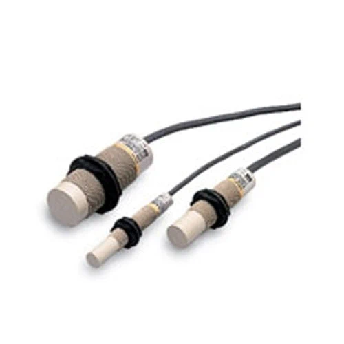
• Product lineup with M12, M18, and M30 models.
• Fixed sensing distance requires no sensitivity adjustment.
Lineup
Sensors
| Appearance | Sensing distance | Output configuration | Model | ||
| Operation mode | |||||
| NO | NC | ||||
|
Unshielded |
M12 | 4 mm | DC 3-wire, NPN | E2K-X4ME1 2M | E2K-X4ME2 2M |
| DC 3-wire, PNP | E2K-X4MF1 2M | E2K-X4MF2 2M | |||
| AC 2-wire | E2K-X4MY1 2M | E2K-X4MY2 2M | |||
| M18 | 8 mm | DC 3-wire, NPN | E2K-X8ME1 2M | E2K-X8ME2 2M | |
| DC 3-wire, PNP | E2K-X8MF1 2M | E2K-X8MF2 2M | |||
| AC 2-wire | E2K-X8MY1 2M | E2K-X8MY2 2M | |||
| M30 | 15 mm | DC 3-wire, NPN | E2K-X15ME1 2M | E2K-X15ME2 2M | |
| DC 3-wire, PNP | E2K-X15MF1 2M | E2K-X15MF2 2M | |||
| AC 2-wire | E2K-X15MY1 2M | E2K-X15MY2 2M | |||
Specifications
| Model | E2K-X4ME[], E2K-X4MF[], E2K-X4MY[] |
E2K-X8ME[], E2K-X8MF[], E2K-X8MY[] |
E2K-X15ME[], E2K-X15MF[], E2K-X15MY[] |
|
|---|---|---|---|---|
| Sensing distance | 4mm ±10% | 8 mm ±10% | 15 mm ±10% | |
| Set distance *1 | 0 to 2.8 mm | 0 to 5.6 mm | 0 to 10 mm | |
| Differential travel | 4% to 20% of sensing distance | |||
| Detectable object | Conductors and dielectrics | |||
| Standard sensing object | Grounded metal plate: 50 × 50 × 1 mm | |||
| Response frequency | E and F Models: 100 Hz, Y Models: 10 Hz | |||
| Power supply voltage *2 (operating voltage range) |
E and F Models: 12 to 24 VDC (10 to 30 VDC) Y Models: 100 to 220 VAC (90 to 250 VAC) |
|||
| Current consumption | E and F Models: 15 mA max. | |||
| Leakage current | Y Models: 2.2 mA max. (Refer to Datasheet.) | |||
| Control output |
Load current | E and F Models: 200 mA max.*2, Y Models: 10 to 200 mA | ||
| Residual voltage |
E and F Models: 2 V max. (Load current: 200 mA, Cable length: 2 m), Y Models: Refer to Engineering Data on Data Sheet. |
|||
| Indicators | E and F Models: Detection indicator (red), Y Models: Operation indicator (red) | |||
| Operation mode (with sensing object approaching) |
E1, F1, and Y1 Models: NO E2, F2, and Y2 Models: NC Refer to the timing charts under I/O Circuit Diagrams on Data Sheet for details. |
|||
| Protection circuits | E and F Models: Reverse polarity protection, Surge suppressor, load short-circuit protection, output reverse polarity protection, Y Models: Surge suppressor |
|||
| Ambient temperature range |
Operating/Storage: -25 to 70°C (with no icing or condensation) |
Operating/Storage: -10 to 55°C (with no icing or condensation) |
||
| Ambient humidity range | Operating/Storage: 35% to 95% (with no condensation) | |||
| Temperature influence | ±20% max. of sensing distance at 23°C in the operating temperature range | |||
| Voltage influence | E and F Models: ±2% max. of sensing distance at rated voltage at rated voltage ±20% Y Models: ±2% max. of sensing distance at rated voltage at rated voltage ±10% |
|||
| Insulation resistance | 50 MΩ min. (at 500 VDC) between current-carrying parts and case | |||
| Dielectric strength | E and F Models: 1,000 VAC, 50/60 Hz for 1 min between current-carrying parts and case Y Models: 2,000 VAC, 50/60 Hz for 1 min between current-carrying parts and case |
|||
| Vibration resistance | Destruction: 10 to 55 Hz, 1.5-mm double amplitude for 2 hours each in X, Y, and Z directions |
|||
| Shock resistance | Destruction: 500 m/s2 3 times each in X, Y, and Z directions | |||
| Degree of protection | IP66 (IEC), in-house standards: oil-resistant | |||
| Connection method | Pre-wired Models (Standard cable length: 2 m) | |||
| Weight (packed state) | Approx. 65 g | Approx. 145 g | Approx. 205 g | |
| Materials | Case | Heat-resistant ABS | ||
| Sensing surface |
||||
| Clamping nuts | Polyacetal | |||
| Accessories | Instruction manual | |||
*1. The above values are sensing distances for the standard sensing object. Refer to Engineering Data on Data Sheet for other materials.
*2. E and F Models (DC switching models): A full-wave rectification power supply of 24 VDC ±20% (average value) can be used.
*2. E and F Models (DC switching models): A full-wave rectification power supply of 24 VDC ±20% (average value) can be used.