USD 241.54
| Item | Specifications | |
|---|---|---|
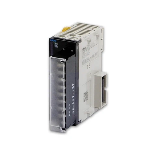
| Model | CJ1W-AD04U | |
| Applicable Controller | CJ/NJ Series | |
| Type of Unit | CJ-series Special I/O Unit | |
| Mounting position | CPU Rack or Expansion Rack | |
| Maximum number of Units | 40 (within the allowable current consumption and power consumption range) | |
| Unit numbers | 00 to 95 (Cannot duplicate Special I/O Unit numbers.) | |
| Areas for exchanging data with the CPU Unit |
Special I/O Unit Area words in the CIO Area (Operation Data) |
10 words/Unit |
| IIsolated-type Universal Input Unit to CPU Unit: All process values, process value alarms (L, H), conversion data enabled flag, input errors, cold junction sensor errors |
||
| Special I/O Unit words in the DM Area (Setting parameter) |
100 words/Unit | |
| CPU Unit to Isolated-type Universal Input Unit: Input type, scaling upper and lower limits, process value alarm setting (L, H), zero/ span adjustment value, alarm ON delay time, alarm hysteresis, Expansion Setting Area settings |
||
| Expansion Setting Area (Expansion Setting parameter) |
1 word/Unit | |
| CPU Unit to Isolated-type Universal Input Unit: Process value alarm output | ||
| Number of inputs | 4 | |
| Input type | Platinum resistance thermometer: Pt100 (JIS, IEC), Pt1000, or JPt100 Thermocouple: K, J, T, L, R, S, or B Current: 4 to 20 mA, or 0 to 20 mA Voltage: 1 to 5 V, 0 to 5 V, or 0 to 10 V Each input can be set independently.Each input can be set independently. |
|
| Scaling (Voltage and current inputs) |
Data to be stored in the allocated words in the CIO area must be scaled (with user- set minimum and maximum values for data and offsets). The inputs are set individually. |
|
| Data storage in the Special I/O Unit Area in the CIO Area |
Voltage inputs and current inputs: The values derived from carrying out the following processing in order of the actual process data in the input range are stored in four digits hexadecimal (binary values) in the allocated words in the Special I/O Unit Area. 1) Scaling → 2) Zero/span adjustment → 3) Output limits Temperature input: The values derived from carrying out the following processing in order of the actual process data in the input range are stored in four digits hexadecimal (binary values) in the allocated words in the Special I/O Unit Area. 1) °C/°F conversion → 2) Zero/span adjustment → 3) Output limits (The stored data is always stored ten times the value of the actual temperature.) |
|
| Accuracy (25 °C) (These values do not include the sensor error.) |
Platinum resistance thermometers: (±0.3% of PV or ±0.8°C, whichever is greater) ±1 digit max. |
|
| Typical thermocouple inputs: (±0.3% of PV or ±1.5°C, whichever is greater) ±1 digit max. Special cases: The accuracy of L is ±2°C ±1 digit max. The accuracy of K and T at -100°C or less is ±2°C ±1 digit max. The accuracy of R and S at 200°C or less is ±3°C 1 digit max. The accuracy of B at 400°C or less is not specified. |
||
| Voltage inputs and current inputs: (±0.3% FS) ±1 digit max. | ||
| Temperature coefficient | ±100 ppm/°C max. (for full scale) | |
| Resolution | 1/12,000 (for voltage or current input) (Please refer to the Input Types and Input Ranges on Data Sheet for details on temperature input.) |
|
| Input signal range | Voltage inputs and current inputs: -5% to 105% of measurable input range set in scaling Temperature inputs: ±20°C or ±20°F for the high or low limits of the sensor range |
|
| Maximum rated input | Voltage Input: ±15 V Current Input: ±30 mA |
|
| Input impedance | Temperature: 10 kΩ min. Voltage Input: 1 MΩ min. Current Input: 250 Ω (rated value) |
|
| Warm-up time | 30 min | |
| Thermocouple inputs | Internal temperature sensor is used for cold junction compensation. | |
| Platinum resistance thermometers |
Measurement method: 3-wire method Allowable lead wire resistance: 20 Ω max. per wire Input detection current: 1.1 mA |
|
| A/D conversion time | 250 ms/4 inputs | |
| Maximum time to store data in CPU Unit |
Conversion period + one CPU Unit cycle | |
| Input error detection | An input error can be detected. (except for voltage and current inputs of 0 to 20 mA, 0 to 5 V, 0 to 10 V) Detection level Temperature input: If the temperature exceeds the high or low limit of the sensor range by 20°C or 20°F. +1 to +5 V: input signal < 0.3 V 4 to 20 mA: input signal < 1.2 mA Input Error Flag turns ON when a disconnection occurs or each input value is out of input range. Process value clamp direction can be specified when input error occurs. |
|
| Process value alarm | Two process value alarms (L, H), hysteresis, and ON-delay timer (0 to 60 s) can be set. Bits of process value alarm can be copied to selectable addresses in the Expansion Setting Area settings. |
|
| Isolation | Between inputs and Controller signals, and between inputs: Isolation by transformer for power supply, and by photocoupler for signals. |
|
| Insulation resistance | 20 MΩ (at 500 V DC) between all inputs | |
| Dielectric strength | Between all inputs: 500 V AC, at 50 or 60 Hz, for 1 min, leakage current 1 mA max. | |
| External connections | Terminal block (detachable) | |
| Indicators | Three LED indicators on front panel (for normal operation, errors detected at the Universal Input Unit, and errors detected at the CPU Unit). |
|
| Unit number settings | Set by rotary switches on front panel, from 0 to 95. | |
| Current consumption (supplied by Power Supply Unit) |
5 V DC at 320 mA max. | |
| Dimensions | 31 × 90 × 65 mm (W × H × D) | |
| Weight | 150 g max. | |