USD 1,107.60
Incremental encoders generate information about position, angle, and rotation counts. The resolution is defined in the number of lines or pulses per rotation, which the encoder transmits to the control unit for each rotation. The current position can be determined by the control unit by counting these pulses. A reference run can be necessary when switching on the machine.
Part Number: 1084000
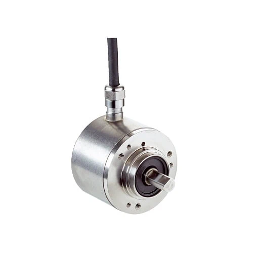
Encoders Model: AFM60I-S4PK262144
| Number of steps per revolution (max. resolution) | 262,144 (18 bit) |
| Number of revolutions | 4,096 (12 bit) |
| Max. resolution (number of steps per revolution x number of revolutions) | 18 bit x 12 bit (262,144 x 4,096) |
| Measuring step deviation | ± 0.002° |
| Error limits G | 0.03° 1) |
| Repeatability standard deviation σr | c |
| Communication interface | SSI |
| Initialization time | 50 ms 1) |
| Position forming time | < 1 µs |
| Code type | Gray |
| Code sequence parameter adjustable | CW/CCW (V/R̅) |
| Interface signals | Clock +, Clock -, Data +, Data – |
| Clock frequency | 2 MHz 2) |
| Set (electronic adjustment) | H-active (L = 0 – 3 V, H = 4,0 – Us V) |
| CW/CCW (counting sequence when turning) | L-active (L = 0 – 1,5 V, H = 2,0 – Us V) |
| Connection type | Cable, 8-wire, universal, 1.5 m 1) |
| Supply voltage | 4.5 … 32 V DC |
| Power consumption | ≤ 0.5 W (without load) |
| Reverse polarity protection | ✔ |
| MTTFd: mean time to dangerous failure | 250 years (EN ISO 13849-1) 2) |
| Mechanical design | Solid shaft, face mount flange |
| Shaft diameter | 10 mm |
| Shaft length | 19 mm |
| Weight | 0.5 kg 1) |
| Shaft material | Stainless steel V2A |
| Flange material | Stainless steel V2A |
| Housing material | Stainless steel V2A |
| Start up torque | 1 Ncm (+20 °C) |
| Operating torque | 0.5 Ncm (+20 °C) |
| Permissible shaft load | 80 N / radial
40 N / axial |
| Operating speed | 9,000 min⁻¹ 2) |
| Moment of inertia of the rotor | 6.2 gcm² |
| Bearing lifetime | 3.0 x 10^9 revolutions |
| Angular acceleration | ≤ 500,000 rad/s² |
| EMC | According to EN 61000-6-2 and EN 61000-6-3 1) |
| Enclosure rating | IP67, shaft side (IEC 60529)
IP67, housing side, cable connection (IEC 60529) |
| Permissible relative humidity | 90 % (Condensation not permitted) |
| Operating temperature range | –40 °C … +100 °C 2)
–30 °C … +100 °C 3) |
| Storage temperature range | –40 °C … +100 °C, without package |
| Resistance to shocks | 100 g, 6 ms (EN 60068-2-27) |
| Resistance to vibration | 10 g, 10 Hz … 2,000 Hz (EN 60068-2-6) |