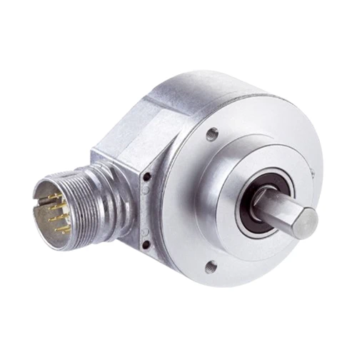
SICK 1037777 AFM60B-S4AA004096 SSI Multiturn Encoder

USD 684.84

AFM60B-S4AA004096 provides SSI Gray-code absolute position with 4,096 steps per turn and 4,096 turns, a 10 mm solid shaft and radial M23 connection.

SKU SICK-1037777 Category
SICK Encoders

SICK AFM60B-S4AA004096 SSI Absolute Multiturn Encoder

BrandSICK
Model IdentifierAFM60B-S4AA004096
Official Part Number1037777

Technical Overview

The SICK AFM60B-S4AA004096 is an SSI absolute multiturn encoder with 4,096 steps per revolution and 4,096 revolutions, giving 12-bit singleturn and 12-bit multiturn information. Gray-code output, adjustable CW/CCW sequence and an electronic SET input support integration with a compatible position controller. Initialization is 50 ms before valid position data, and the SSI clock supports up to 2 MHz with the specified LOW-level duration. Its solid 10 mm shaft has a flat and 19 mm length, with a face-mount flange and radial M23 twelve-pin connector. The 4.5–32 V device uses at most 0.7 W without load; mechanical speed and ambient design account for specified self-heating.

SSI Gray-code multiturn absolute encoder with 4,096 steps ×4,096 revolutions, 10 mm solid shaft, face-mount flange and radial M23 twelve-pin connector.

Key Features

  • Absolute multiturn measurement: 4,096 steps per revolution ×4,096 revolutions
  • 12-bit singleturn and 12-bit multiturn resolution
  • SSI interface with Gray code; adjustable CW/CCW sequence
  • 50 ms initialization; <1 µs position forming time
  • SSI clock ≤2 MHz; minimum Clock+ LOW duration 250 ns
  • H-active electronic SET and L-active CW/CCW input
  • 10 mm solid stainless-steel shaft with flat and 19 mm length; face-mount flange
  • Radial M23 twelve-pin male connector; 4.5–32 V supply
  • ≤0.7 W without load; reverse-polarity protection
  • IP65 shaft and IP67 housing with mating connector; observe shielded-cable and stationary-cable conditions

Provide absolute shaft angle and revolution information over SSI, with electronic adjustment and selectable counting direction for external position control.

Technical Specification Matrix

ParameterValue
Encoder typeAbsolute multiturn
Steps per revolution4,096, 12 bit
Number of revolutions4,096, 12 bit
Maximum resolution12 bit ×12 bit; 4,096 steps per turn ×4,096 revolutions
Error limits G0.05°; symmetrical upper/lower error-limit position, DIN ISO 1319-1; installation dependent
RepeatabilityStandard deviation σr 0.002°, DIN ISO 55350-13; 68.3% of measured values within specified area
Communication interfaceSSI
Code typeGray
Code sequenceCW/CCW adjustable
Initialization time50 ms before valid positional data can be read
Position forming time<1 µs
Clock frequency≤2 MHz; minimum Clock+ LOW level 250 ns
Electronic SETH-active: LOW 0–3 V; HIGH 4 V to Us
CW/CCW inputL-active: LOW 0–1.5 V; HIGH 2 V to Us
Power supply4.5–32 V
Power consumption≤0.7 W without load
Reverse-polarity protectionYes
ConnectionRadial M23 twelve-pin male connector
M23 pin assignment1=GND; 2=Data+; 3=Clock+; 4/5/6/7=NC; 8=Us; 9=SET; 10=Data−; 11=Clock−; 12=V/R counting direction
Shield connectionShield connected to encoder housing; connect to ground at control side
Mechanical designSolid shaft, face-mount flange
Shaft diameter and length10 mm diameter; 19 mm length; with flat
Shaft materialStainless steel
Flange materialAluminum
Housing materialDie-cast aluminum
Start-up torque<0.5 Ncm at +20 °C
Operating torque<0.3 Ncm at +20 °C
Permissible shaft load80 N radial; 40 N axial
Operating speed≤9,000 min⁻¹; allow self-heating of 3.3 K per 1,000 rpm when designing operating temperature range
Rotor moment of inertia6.2 gcm²
Bearing lifetime3 ×10⁹ revolutions
Angular acceleration≤500,000 rad/s²
EMCEN 61000-6-2 and EN 61000-6-3, achieved with shielded cables
IP ratingIP65 shaft side; IP67 housing side with mating connector fitted, IEC 60529
Relative humidity90%; condensation not permitted
Operating temperature−40 to +100 °C with stationary cable; observe speed-related self-heating allowance
Storage temperature−40 to +100 °C without packaging
Shock resistance70 g for 6 ms, EN 60068-2-27
Vibration resistance30 g, 10–2,000 Hz, EN 60068-2-6
MTTFD250 years, EN ISO 13849-1; nominal component loads, average ambient 40 °C and 8,760 h/year; all electronic failures counted as dangerous; standard product, not a safety component
Physical Weight (kg)0.3

Industrial Applications

1. Reporting the angular position of an indexing table

An indexing table can couple the encoder’s solid shaft to its rotary drive and read absolute angular information through compatible SSI electronics. The 4,096 steps per revolution distinguish positions within one turn, while electronic SET and counting-direction inputs align the reported coordinate with the machine reference. Setup checks installation-dependent accuracy, coupling loads and the required initialization interval.

Problem Solved

An absolute angular reference helps external indexing control distinguish table positions, with the reported coordinate aligned to the machine and checked against the installed measurement accuracy.

Indexing angle SSI Gray code Coordinate setup

2. Tracking screw-driven carriage travel across multiple turns

A screw-driven carriage can couple its rotating drive to the encoder and use the 4,096-revolution multiturn range to distinguish successive shaft turns. External control converts the SSI value into linear position using the actual screw pitch and mechanical ratio. Commissioning establishes counting direction and coordinate adjustment, while checking the shaft loads and the complete travel against the encoder’s representable range.

Problem Solved

Multiturn information helps external position control distinguish carriage locations that share the same shaft angle, using the commissioned screw-drive conversion across successive revolutions.

Multiturn carriage Absolute position Mechanical conversion

3. Establishing a position coordinate during machine commissioning

Commissioning staff can place a coupled axis at its chosen machine reference and use the electronic SET input to align the absolute position coordinate. A compatible controller reads SSI Gray-code data after initialization and verifies the reported direction during controlled movement. Electrical setup observes SET and CW/CCW input levels, clock timing, shielding and the documented M23 pin assignment.

Problem Solved

Electronic coordinate adjustment helps commissioning align reported shaft position with the machine reference, using verified input levels and SSI wiring before the axis enters normal operation.

Commissioning coordinate Electronic SET SSI timing

Select your currency