1. CNC Spindle Runout and Taper Alignment
Mounting a dial test indicator via the dovetail groove to verify the internal taper runout of a CNC spindle. The articulating jointed arm is extended to position the indicator probe precisely inside the spindle head. The operator rotates the spindle manually to detect radial runout.
Problem SolvedEliminates indicator displacement or flex during spindle rotation. The centralized mechanical locking mechanism completely rigidifies the joints, ensuring sub-micron accuracy without micro-deflections.
CNC SpindleRunout MetrologyDovetail GrooveArticulated Arm RigidityMechanical Joint Lock
2. Lathe Chuck Cylindrical Workpiece Concentricity Check
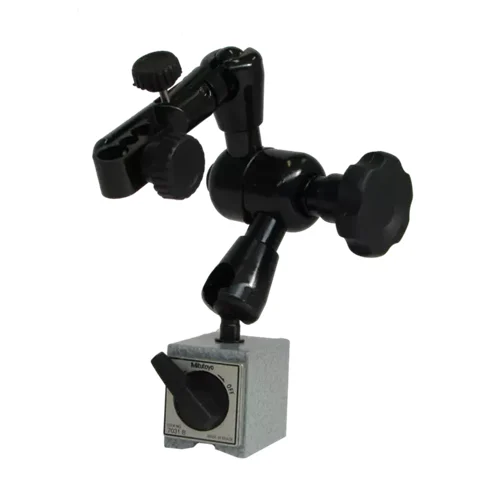
Placing the V-groove magnetic base onto the curved headstock or carriage of a lathe. By utilizing the 300 N holding force, the stand holds a dial indicator perpendicular to a chucked cylindrical shaft while the workpiece is rotated to verify concentricity and alignment before cutting.
Problem SolvedSolves the problem of mounting stands on round or uneven machine castings. The compact 36x30x36 mm magnetic base with built-in V-groove ensures a stable, non-slip grip under vibrations.
Concentricity AlignmentLathe MachiningV-Groove Base Stability300 N Magnetic ForceIndicator Setup
3. Surface Plate Parallelism and Flatness Inspection
Utilizing the stand on steel surface plates or reference fixtures to carry out high-precision flatness and height mapping of machined parts. The operator uses the fine adjustment wheel (±4°) to establish a zero-reference baseline on the indicator face with absolute control.
Problem SolvedPrevents the awkwardness and inaccuracy of coarse manual indicator positioning. The fine feed wheel enables rapid, microscopic leveling of the stylus, eliminating setup drift and saving inspection time.
Metrology LabParallelism MappingFine Adjustment Feed WheelStem Hole ClampingFlatness Verification