$ 292.25 – $ 1,086.75Price range: $ 292.25 through $ 1,086.75
| Product name |
Specification | Model | ||||||
|---|---|---|---|---|---|---|---|---|
| Number of chan- nels *1 |
External inputs |
External outputs |
Maximum pulse output speed |
I/O refreshing method |
Number of I/O entry mappings |
Control output interface |
||
| Pulse Output Unit |
1 (NPN) |
2 (NPN) | 1 (NPN) | 500 kpps | • Synchro- nous I/O refreshing • Task period prioritized refreshing *2 |
1/1 | Open collector output |
NX-PG0112 |
| 1 (PNP) |
2 (PNP) | 1 (PNP) | NX-PG0122 | |||||
| 2 | 5 inputs/ CH (NPN) |
3 outputs/ CH (NPN) |
4 Mpps | 2/2 | Line driver output |
NX-PG0232-5 | ||
| 5 inputs/ CH (PNP) |
3 outputs/ CH (PNP) |
NX-PG0242-5 | ||||||
| 4 | 5 inputs/ CH (NPN) |
3 outputs/ CH (NPN) |
4/4 | NX-PG0332-5 | ||||
| 5 inputs/ CH (PNP) |
3 outputs/ CH (PNP) |
NX-PG0342-5 | ||||||
*1. This is the number of pulse output channels.
*2. Unit version 1.2 or later and an NX-ECC203 EtherCAT Coupler Unit are required.
| Item | Specification | |
|---|---|---|
| Enclosure | Mounted in a panel | |
| Grounding method | Ground to less than 100 Ω | |
| Operating environment |
Ambient operating temperature |
0 to 55°C |
| Ambient operating humidity |
10% to 95% (with no condensation or icing) | |
| Atmosphere | Must be free from corrosive gases. | |
| Ambient storage temperature |
-25 to 70°C (with no condensation or icing) | |
| Altitude | 2,000 m max. | |
| Pollution degree | Pollution degree 2 or less: Meets IEC 61010-2-201. | |
| Noise immunity | Conforms to IEC61000-4-4, 2 kV (power supply line) | |
| Overvoltage category | Category II: Meets IEC 61010-2-201. | |
| EMC immunity level | Zone B | |
| Vibration resistance | Conforms to IEC 60068-2-6. 5 to 8.4 Hz with 3.5-mm amplitude, 8.4 to 150 Hz, acceleration of 9.8 m/s2, 100 min each in X, Y, and Z directions (10 sweeps of 10 min each = 100 min total) |
|
| Shock resistance | Conforms to IEC 60068-2-27. 147 m/s2, 3 times each in X, Y, and Z directions | |
| Applicable standards * | cULus: Listed (UL508) or Listed (UL 61010-2-201), ANSI/ISA 12.12.01, EU: EN 61131-2, C-Tick or RCM, KC Registration, NK, LR |
|
* Ask your OMRON representative for the most recent applicable standards for each model.
| Unit name | Pulse Output Unit | Model | NX-PG0112 | |
|---|---|---|---|---|
| Number of axes | 1 | Type of external connections |
Screwless clamping terminal block (16 terminals) |
|
| I/O refreshing method *1 | Synchronous I/O refreshing or task period prioritized refreshing | |||
| Indicators |  |
I/O signals | Inputs: 2, External inputs Outputs: 3, The outputs are the forward direction pulse output, reverse direction pulse output, and external output (one of each output). |
|
| Control method | Open-loop control through pulse string output | |||
| Controlled drive | Servo drive with a pulse string input or a stepper motor drive | |||
| Pulse output form | Open collector output | |||
| Control unit | Pulses | |||
| Maximum pulse output speed |
500kpps | |||
| Pulse output method | Forward/reverse direction pulse outputs or pulse + direction outputs | |||
| Position control range | -2,147,483,648 to 2,147,483,647 pulses | |||
| Velocity control range | 1 to 500,000 pps | |||
| Positioning *2 | ||||
| Single-axis position control |
Absolute positioning, relative positioning, and interrupt feeding | |||
| Single-axis velocity control |
Velocity control (velocity feeding in Position Control Mode) | |||
| Single-axis synchronized control |
Cam operation and gear operation | |||
| Single-axis manual operation |
Jogging | |||
| Auxiliary function for single-axis control |
Homing, stopping, and override changes | |||
| External input specifications | ||||
| Input voltage | 20.4 to 28.8 VDC (24 VDC +20%/-15%) |
ON voltage/ ON current |
15 VDC min./3 mA min. | |
| Input current | 4.6 mA typical (24 VDC) | OFF voltage/OFF current |
4.0 VDC max./1 mA max. | |
| ON/OFF response time | 1 μs max./2 μs max. | |||
| Internal I/O common processing |
NPN | |||
| Pulse output and external output specifications | ||||
| Rated voltage | 24 VDC | |||
| Load voltage range | 15 to 28.8 VDC | Residual voltage | 1.0 V max. | |
| Maximum load current | 30mA | Leakage current | 0.1 mA max. | |
| ON/OFF response time | Pulse output: Refer to “NX-series Position Interface Units User’s Manual (W524-E1)”. External output: 5 μs max./5 μs max. |
|||
| Internal I/O common processing |
NPN | |||
| Dimensions | 12 × 100 × 71 mm (W×H×D) |
Isolation method |
External inputs: Photocoupler isolation External outputs: Digital isolator |
|
| Insulation resistance | 20 MΩ min. between isolated circuits (at 100 VDC) |
Dielectric strength |
510 VAC between isolated circuits for 1minute with leakage current of 5 mA max. |
|
| I/O power supply source | Supplied from the NX bus. 20.4 to 28.8 VDC (24 VDC +20%/-15%) |
Current capacity of I/O power supply terminals |
IOV: 0.1 A max. per terminal IOG: 0.1 A max. per terminal |
|
| NX Unit power consumption |
• Connected to a CPU Unit 1.15 W max. • Connected to a Commu- nications Coupler Unit 0.80 W max. |
Current consumption from I/O power supply |
20 mA max. | |
| Weight | 70 g max. | Cable length | 3 m max. | |
| Circuit layout |  |
|||
| Installation orientation and restrictions |
Installation orientation: • Connected to a CPU Unit: Possible in upright installation. • Connected to a Communications Coupler Unit: Possible in 6 orientations. Restrictions: There are no restrictions. |
|||
| Terminal connection diagram |
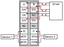 |
|||
| Failure detection | None | Protection | None | |
*1. The I/O refreshing method is automatically set according to the connected Communications Coupler Unit and CPU Unit.
*2. These functions are supported when you also use the MC Function Module in the NJ/NX-series CPU Unit or the NY-
series Industrial PC.
For details, refer to the motion control user’s manual for the connected CPU Unit or Industrial PC.
A Pulse Output Unit only outputs pulses during the control period based on commands received at a fixed period.
Target position calculations (distribution calculations) for acceleration/deceleration control or for each control period must
be performed on the Controller.
| Unit name | Pulse Output Unit | Model | NX-PG0232-5 | |
|---|---|---|---|---|
| Number of channels | 2 channels | Type of external connections |
MIL connector (34 terminals ×1) | |
| I/O refreshing method *1 | Synchronous I/O refreshing or task period prioritized refreshing | |||
| Indicators |  |
I/O signals | Inputs: 5 per channel. External inputs *2 Outputs: 5 per channel. 1 forward direction pulse output, 1 reverse direction pulse output, and 3 external outputs (per channel) *3 |
|
| Control method | Open-loop control through pulse string output | |||
| Controlled drive | Servo drive with a pulse string input or a stepper motor drive | |||
| Pulse output form | Line driver output | |||
| Unit of control | Pulses | |||
| Maximum pulse output speed |
4 Mpps | |||
| Pulse output method | Forward/reverse direction pulse outputs, Pulse + direction outputs, or Phase differential pulse output multiplication x1/2/4 |
|||
| Position control range | -2,147,483,648 to 2,147,483,647 pulses | |||
| Velocity control range | 1 to 4,000,000 pps | |||
| Positioning *4 | ||||
| Single-axis position control |
Absolute positioning, relative positioning, and interrupt feeding | |||
| Single-axis velocity control |
Velocity control (velocity feeding in Position Control Mode) | |||
| Single-axis synchronized control |
Cam operation and gear operation | |||
| Single-axis manual operation |
Jogging | |||
| Auxiliary function for single-axis control |
Homing, stopping, and override changes | |||
| External input specifications (except for line receiver inputs) | ||||
| Input voltage | 21.6 to 26.4 VDC (24 VDC +10%, -10%) |
ON voltage/ ON current |
15 VDC min./3 mA min. | |
| Input current | 4.6 mA typical (24 VDC) | OFF voltage/OFF current |
4.0 VDC max./1 mA max. | |
| ON/OFF response time | External inputs 0 and 1: 1 μs max./2 μs max. External inputs 2 to 4: 20 μs max./400 μs max. |
|||
| Internal I/O common processing |
NPN | |||
| External input specifications (line receiver inputs) | ||||
| Input voltage | EIA standard RS-422-A line driver levels |
High level input voltage | VIT+: 0.1 V min. | |
| Input impedance | 120 Ω ± 5% | Low level input voltage | VIT-: -0.1 V max. | |
| Hysteresis voltage | Vhys (VIT+ – VIT-): 60 mV | |||
| Line driver output specifications | ||||
| Output voltage | RS-422-A line driver level (equivalent to AM26C31) | |||
| Maximum load current | 20 mA | |||
| Maximum output frequency |
4 Mpps | |||
| External output specifications | ||||
| Rated voltage | 24 VDC | |||
| Load voltage range | 15 to 28.8 VDC | Residual voltage | 1.0 V max. | |
| Maximum load current | 30mA | Leakage current | 0.1 mA max. | |
| ON/OFF response time | External output 0: 5 μs max./5 μs max. External outputs 1 and 2: 0.5 ms max./1 ms max. |
|||
| Internal I/O common processing |
NPN | |||
| Dimensions | 30 × 100 × 71 mm
(W×H×D) |
Isolation method |
External inputs: Photocoupler isolation External outputs: Digital isolator |
|
| Insulation resistance | 20 MΩ min. between isolated circuits (at 100 VDC) |
Dielectric strength |
510 VAC between isolated circuits for 1 minute at a leakage current of 5 mA max. |
|
| I/O power supply source | Supply from external source 20.4 to 28.8 VDC(24 VDC +20%, -15%) |
Current capacity of I/O power supply terminals |
Without I/O power supply terminals | |
| NX Unit power consumption |
• Connected to a CPU Unit 1.55 W max. • Connected to a Communi- cations Coupler Unit 1.20 W max. |
Current consumption from I/O power supply |
50 mA max. | |
| Weight | 110 g max. | Cable length | Line driver outputs: 10 m max. Other I/O: 3 m max. |
|
| Circuit layout |  |
|||
| Installation orientation and restrictions |
Installation orientation: • Connected to a CPU Unit: Possible in upright installation. • Connected to a Communications Coupler Unit: Possible in 6 orientations. Restrictions: The number of external inputs that can be always ON is restricted as shown below. 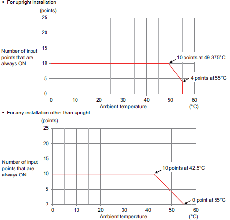 |
|||
| Terminal connection diagram |
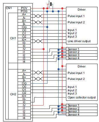 |
|||
| Failure detection | None | Protection | None | |
*1. The I/O refreshing method is automatically set according to the connected Communications Coupler Unit and CPU Unit.
*2. You can use the external input 0 as a latch input.
*3. You can use the external output 0 as an error counter reset output.
*4. These functions are supported when you also use the MC Function Module in the NJ/NX-series CPU Unit or the NY-
series Industrial PC.
For details, refer to the motion control user’s manual for the connected CPU Unit or Industrial PC.
A Pulse Output Unit only outputs pulses during the control period based on commands received at a fixed period.
Target position calculations (distribution calculations) for acceleration/deceleration control or for each control period must
be performed on the Controller.
| Unit name | Pulse Output Unit | Model | NX-PG0242-5 | |
|---|---|---|---|---|
| Number of channels | 2 channels | Type of external connections |
MIL connector (34 terminals ×1) | |
| I/O refreshing method *1 | Synchronous I/O refreshing or task period prioritized refreshing | |||
| Indicators |  |
I/O signals | Inputs: 5 per channel. External inputs *2 Outputs: 5 per channel. 1 forward direction pulse output, 1 reverse direction pulse output, and 3 external outputs (per channel) *3 |
|
| Control method | Open-loop control through pulse string output | |||
| Controlled drive | Servo drive with a pulse string input or a stepper motor drive | |||
| Pulse output form | Line driver output | |||
| Unit of control | Pulses | |||
| Maximum pulse output speed |
4 Mpps | |||
| Pulse output method | Forward/reverse direction pulse outputs, Phase + direction outputs, or Phase differential pulse output multiplication x1/2/4 |
|||
| Position control range | -2,147,483,648 to 2,147,483,647 pulses | |||
| Velocity control range | 1 to 4,000,000 pps | |||
| Positioning *4 | ||||
| Single-axis position control |
Absolute positioning, relative positioning, and interrupt feeding | |||
| Single-axis velocity control |
Velocity control (velocity feeding in Position Control Mode) | |||
| Single-axis synchronized control |
Cam operation and gear operation | |||
| Single-axis manual operation |
Jogging | |||
| Auxiliary function for single-axis control |
Homing, stopping, and override changes | |||
| External input specifications (except for line receiver inputs) | ||||
| Input voltage | 21.6 to 26.4 VDC (24 VDC +10%, -10%) |
ON voltage/ ON current |
15 VDC min./3 mA min. | |
| Input current | 4.6 mA typical (24 VDC) | OFF voltage/OFF current |
4.0 VDC max./1 mA max. | |
| ON/OFF response time | External inputs 0 and 1: 1 μs max./2 μs max. External inputs 2 to 4: 20 μs max./400 μs max. |
|||
| Internal I/O common processing |
PNP | |||
| External input specifications (line receiver inputs) | ||||
| Input voltage | EIA standard RS-422-A line driver levels |
High level input voltage | VIT+: 0.1 V min. | |
| Input impedance | 120 Ω ± 5% | Low level input voltage | VIT-: -0.1 V max. | |
| Hysteresis voltage | Vhys (VIT+ – VIT-): 60 mV | |||
| Line driver output specifications | ||||
| Output voltage | RS-422-A line driver level (equivalent to AM26C31) | |||
| Maximum load current | 20 mA | |||
| Maximum output frequency |
4 Mpps | |||
| External output specifications | ||||
| Rated voltage | 24 VDC | |||
| Load voltage range | 15 to 28.8 VDC | Residual voltage | 1.0 V max. | |
| Maximum load current | 30mA | Leakage current | 0.1 mA max. | |
| ON/OFF response time | External output 0: 5 μs max./200 μs max. External outputs 1 and 2: 0.5 ms max./1 ms max. |
|||
| Internal I/O common processing |
PNP | |||
| Dimensions | 30 × 100 × 71 mm
(W×H×D) |
Isolation method |
External inputs: Photocoupler isolation External outputs: Digital isolator |
|
| Insulation resistance | 20 MΩ min. between isolated circuits (at 100 VDC) |
Dielectric strength |
510 VAC between isolated circuits for 1 minute at a leakage current of 5 mA max. |
|
| I/O power supply source | Supply from external source 20.4 to 28.8 VDC(24 VDC +20%, -15%) |
Current capacity of I/O power supply terminals |
Without I/O power supply terminals | |
| NX Unit power consumption |
• Connected to a CPU Unit 1.55 W max. • Connected to a Commu- nications Coupler Unit 1.20 W max. |
Current consumption from I/O power supply |
50 mA max. | |
| Weight | 110 g max. | Cable length | Line driver outputs: 10 m max. Other I/O: 3 m max. |
|
| Circuit layout | 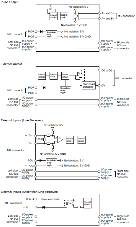 |
|||
| Installation orientation and restrictions |
Installation orientation: • Connected to a CPU Unit: Possible in upright installation. • Connected to a Communications Coupler Unit: Possible in 6 orientations. Restrictions: The number of external inputs that can be always ON is restricted as shown below. 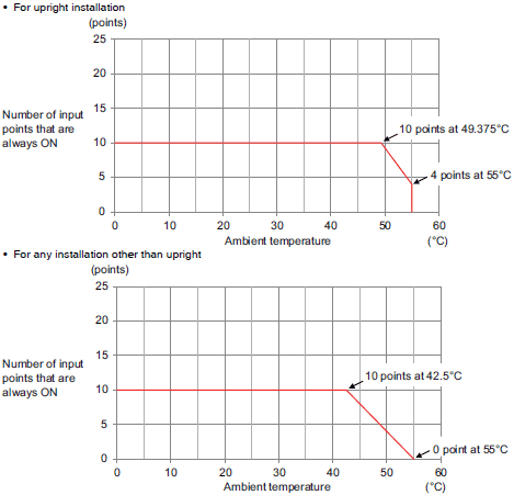 |
|||
| Terminal connection diagram |
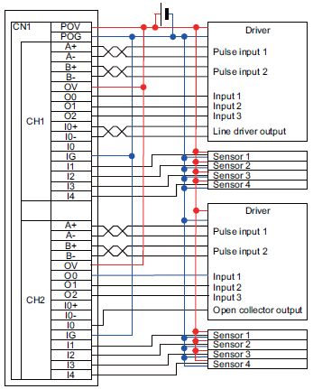 |
|||
| Failure detection | None | Protection | None | |
*1. The I/O refreshing method is set according to the connected Communications Coupler Unit and CPU Unit.
*2. You can use the external input 0 as a latch input.
*3. You can use the external output 0 as an error counter reset output.
*4. These functions are supported when you also use the MC Function Module in the NJ/NX-series CPU Unit or the NY-
series Industrial PC.
For details, refer to the motion control user’s manual for the connected CPU Unit or Industrial PC.
A Pulse Output Unit only outputs pulses during the control period based on commands received at a fixed period.
Target position calculations (distribution calculations) for acceleration/deceleration control or for each control period must
be performed on the Controller.
| Unit name | Pulse Output Unit | Model | NX-PG0332-5 | |
|---|---|---|---|---|
| Number of channels | 4 channels | Type of external connections |
MIL connector (34 terminals ×2) | |
| I/O refreshing method *1 | Synchronous I/O refreshing or task period prioritized refreshing | |||
| Indicators |  |
I/O signals | Inputs: 5 per channel. External inputs*2 Outputs: 5 per channel. 1 forward direction pulse output, 1 reverse direction pulse output, and 3 external outputs (per channel)*3 |
|
| Control method | Open-loop control through pulse string output | |||
| Controlled drive | Servo drive with a pulse string input or a stepper motor drive | |||
| Pulse output form | Line driver output | |||
| Unit of control | Pulses | |||
| Maximum pulse output speed |
4 Mpps | |||
| Pulse output method | Forward/reverse direction pulse outputs, Pulse + direction outputs, or Phase differential pulse output multiplication x1/2/4 |
|||
| Position control range | -2,147,483,648 to 2,147,483,647 pulses | |||
| Velocity control range | 1 to 4,000,000 pps | |||
| Positioning *4 | ||||
| Single-axis position control |
Absolute positioning, relative positioning, and interrupt feeding | |||
| Single-axis velocity control |
Velocity control (velocity feeding in Position Control Mode) | |||
| Single-axis synchronized control |
Cam operation and gear operation | |||
| Single-axis manual operation |
Jogging | |||
| Auxiliary function for single-axis control |
Homing, stopping, and override changes | |||
| External input specifications (except for line receiver inputs) | ||||
| Input voltage | 21.6 to 26.4 VDC (24 VDC +10%, -10%) |
ON voltage/ ON current |
15 VDC min./3 mA min. | |
| Input current | 4.6 mA typical (24 VDC) | OFF voltage/OFF current |
4.0 VDC max./1 mA max. | |
| ON/OFF response time | External inputs 0 and 1: 1 μs max./2 μs max. External inputs 2 to 4: 20 μs max./400 μs max. |
|||
| Internal I/O common processing |
NPN | |||
| External input specifications (line receiver inputs) | ||||
| Input voltage | EIA standard RS-422-A line driver levels |
High level input voltage | VIT+: 0.1 V min. | |
| Input impedance | 120 Ω ± 5% | Low level input voltage | VIT-: -0.1 V max. | |
| Hysteresis voltage | Vhys (VIT+ – VIT-): 60 mV | |||
| Line driver output specifications | ||||
| Output voltage | RS-422-A line driver level (equivalent to AM26C31) | |||
| Maximum load current | 20 mA | |||
| Maximum output frequency |
4 Mpps | |||
| External output specifications | ||||
| Rated voltage | 24 VDC | |||
| Load voltage range | 15 to 28.8 VDC | Residual voltage | 1.0 V max. | |
| Maximum load current | 30mA | Leakage current | 0.1 mA max. | |
| ON/OFF response time | External output 0: 5 μs max./200 μs max. External outputs 1 and 2: 0.5 ms max./1 ms max. |
|||
| Internal I/O common processing |
NPN | |||
| Dimensions | 30 × 100 × 71 mm
(W×H×D) |
Isolation method |
External inputs: Photocoupler isolation External outputs: Digital isolator |
|
| Insulation resistance | 20 MΩ min. between isolated circuits (at 100 VDC) |
Dielectric strength |
510 VAC between isolated circuits for 1 minute at a leakage current of 5 mA max. |
|
| I/O power supply source | Supply from external source 20.4 to 28.8 VDC(24 VDC +20%, -15%) |
Current capacity of I/O power supply terminals |
Without I/O power supply terminals | |
| NX Unit power consumption |
• Connected to a CPU Unit 1.65 W max. • Connected to a Communi- cations Coupler Unit 1.30 W max. |
Current consumption from I/O power supply |
50 mA/CN max. | |
| Weight | 150 g max. | Cable length | Line driver outputs: 10 m max. Other I/O: 3 m max. |
|
| Circuit layout | 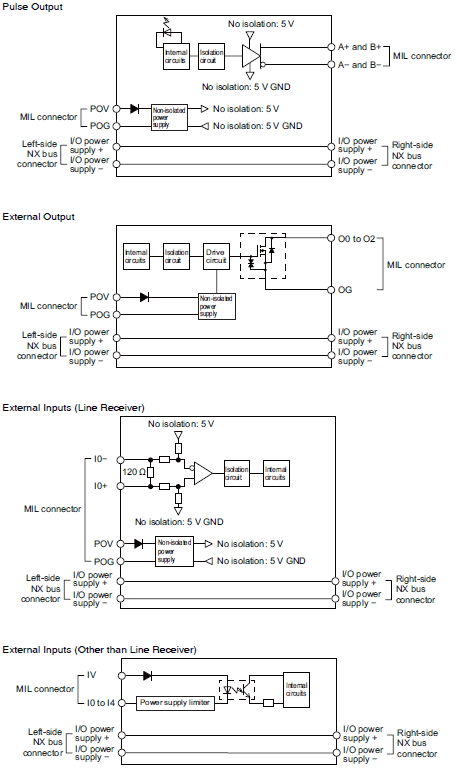 |
|||
| Installation orientation and restrictions |
Installation orientation: • Connected to a CPU Unit: Possible in upright installation. • Connected to a Communications Coupler Unit: Possible in 6 orientations. Restrictions: The number of external inputs that can be always ON is restricted as shown below. 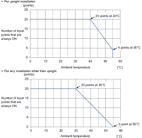 |
|||
| Terminal connection diagram |
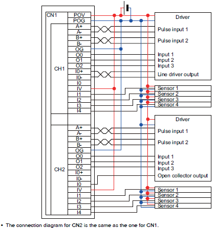 |
|||
| Failure detection | None | Protection | None | |
*1. The I/O refreshing method is set according to the connected Communications Coupler Unit and CPU Unit.
*2. You can use the external input 0 as a latch input.
*3. You can use the external output 0 as an error counter reset output.
*4. These functions are supported when you also use the MC Function Module in the NJ/NX-series CPU Unit or the NY-
series Industrial PC.
For details, refer to the motion control user’s manual for the connected CPU Unit or Industrial PC.
A Pulse Output Unit only outputs pulses during the control period based on commands received at a fixed period.
Target position calculations (distribution calculations) for acceleration/deceleration control or for each control period must
be performed on the Controller.
| Unit name | Pulse Output Unit | Model | NX-PG0342-5 | |
|---|---|---|---|---|
| Number of channels | 4 channels | Type of external connections |
MIL connector (34 terminals ×2) | |
| I/O refreshing method *1 | Synchronous I/O refreshing or task period prioritized refreshing | |||
| Indicators |  |
I/O signals | Inputs: 5 per channel. External inputs *2 Outputs: 5 per channel. 1 forward direction pulse output, 1 reverse direction pulse output, and 3 external outputs (per channel) *3 |
|
| Control method | Open-loop control through pulse string output | |||
| Controlled drive | Servo drive with a pulse string input or a stepper motor drive | |||
| Pulse output form | Line driver output | |||
| Unit of control | Pulses | |||
| Maximum pulse output speed |
4 Mpps | |||
| Pulse output method | Forward/reverse direction pulse outputs, Pulse + direction outputs, or Phase differential pulse output multiplication x1/2/4 |
|||
| Position control range | -2,147,483,648 to 2,147,483,647 pulses | |||
| Velocity control range | 1 to 4,000,000 pps | |||
| Positioning *4 | ||||
| Single-axis position control |
Absolute positioning, relative positioning, and interrupt feeding | |||
| Single-axis velocity control |
Velocity control (velocity feeding in Position Control Mode) | |||
| Single-axis synchronized control |
Cam operation and gear operation | |||
| Single-axis manual operation |
Jogging | |||
| Auxiliary function for single-axis control |
Homing, stopping, and override changes | |||
| External input specifications (except for line receiver inputs) | ||||
| Input voltage | 21.6 to 26.4 VDC (24 VDC +10%, -10%) |
ON voltage/ ON current |
15 VDC min./3 mA min. | |
| Input current | 4.6 mA typical (24 VDC) | OFF voltage/OFF current |
4.0 VDC max./1 mA max. | |
| ON/OFF response time | External inputs 0 and 1: 1 μs max./2 μs max. External inputs 2 to 4: 20 μs max./400 μs max. |
|||
| Internal I/O common processing |
PNP | |||
| External input specifications (line receiver inputs) | ||||
| Input voltage | EIA standard RS-422-A line driver levels |
High level input voltage | VIT+: 0.1 V min. | |
| Input impedance | 120 Ω ± 5% | Low level input voltage | VIT-: -0.1 V max. | |
| Hysteresis voltage | Vhys (VIT+ – VIT-): 60 mV | |||
| Line driver output specifications | ||||
| Output voltage | RS-422-A line driver level (equivalent to AM26C31) | |||
| Maximum load current | 20 mA | |||
| Maximum output frequency |
4 Mpps | |||
| External output specifications | ||||
| Rated voltage | 24 VDC | |||
| Load voltage range | 15 to 28.8 VDC | Residual voltage | 1.0 V max. | |
| Maximum load current | 30mA | Leakage current | 0.1 mA max. | |
| ON/OFF response time | External output 0: 5 μs max./200 μs max. External outputs 1 and 2: 0.5 ms max./1 ms max. |
|||
| Internal I/O common processing |
PNP | |||
| Dimensions | 30 × 100 × 71 mm
(W×H×D) |
Isolation method |
External inputs: Photocoupler isolation External outputs: Digital isolator |
|
| Insulation resistance | 20 MΩ min. between isolated circuits (at 100 VDC) |
Dielectric strength |
510 VAC between isolated circuits for 1 minute at a leakage current of 5 mA max. |
|
| I/O power supply source | Supply from external source 20.4 to 28.8 VDC(24 VDC +20%, -15%) |
Current capacity of I/O power supply terminals |
Without I/O power supply terminals | |
| NX Unit power consumption |
• Connected to a CPU Unit 1.65 W max. • Connected to a Communi- cations Coupler Unit 1.30 W max. |
Current consumption from I/O power supply |
50 mA/CN max. | |
| Weight | 150 g max. | Cable length | Line driver outputs: 10 m max. Other I/O: 3 m max. |
|
| Circuit layout | 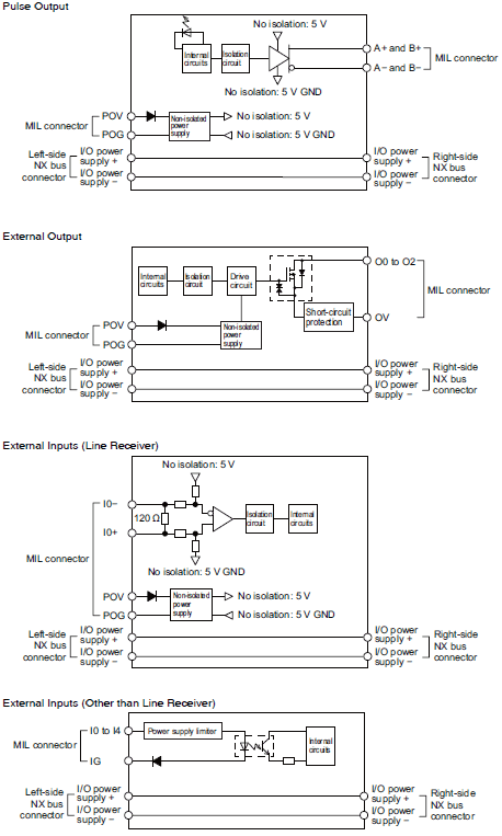 |
|||
| Installation orientation and restrictions |
Installation orientation: • Connected to a CPU Unit: Possible in upright installation. • Connected to a Communications Coupler Unit: Possible in 6 orientations. Restrictions: The number of external inputs that can be always ON is restricted as shown below.  |
|||
| Terminal connection diagram |
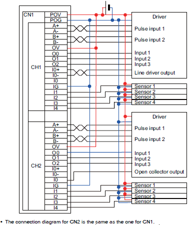 |
|||
| Failure detection | None | Protection | None | |
*1. The I/O refreshing method is set according to the connected Communications Coupler Unit and CPU Unit.
*2. You can use the external input 0 as a latch input.
*3. You can use the external output 0 as an error counter reset output.
*4. These functions are supported when you also use the MC Function Module in the NJ/NX-series CPU Unit or the NY-
series Industrial PC.
For details, refer to the motion control user’s manual for the connected CPU Unit or Industrial PC.
A Pulse Output Unit only outputs pulses during the control period based on commands received at a fixed period.
Target position calculations (distribution calculations) for acceleration/deceleration control or for each control period must
be performed on the Controller.