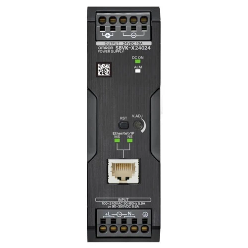
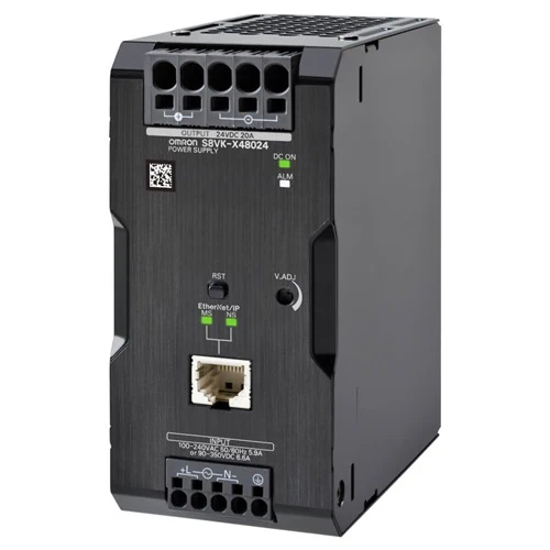
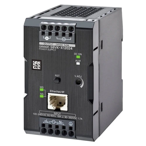
S8VK-X – Without Indication Monitor – Omron Switch Mode Power Supply

$ 261.58$ 667.70

SKU: N/A

Ratings, Characteristics, and Functions

Power rating 30 W 60W
Rated output voltage (DC) 5 V 12 V 24 V
Indication monitor None None None
Efficiency * 115 VAC input 78% typ. 85% typ. 85% typ.
230 VAC input 77% typ. 86% typ. 86% typ.
Input
conditions
Voltage range * Single-phase, 85 to 264 VAC, 90 to 350 VDC, 265 to 300 VAC
(1 second)
Frequency * 50/60 Hz (47 to 450 Hz)
Input current * 115 VAC input 0.53 A typ. 0.99 A typ. 1.1 A typ.
230 VAC input 0.32 A typ. 0.61 A typ. 0.67 A typ.
Power factor *
Leakage
current *
115 VAC input 0.5 mA max.
230 VAC input 1 mA max.
Inrush
current *
115 VAC input 16 A typ.
230 VAC input 32 A typ.
Output
characteristics
Rated output current 5 A 4.5 A 2.5 A
Rated output power 25 W 54 W 60 W
Maximum boost current 6 A 5.4 A 3 A
Voltage adjustment range * 4.5 to 5.8V (with V. ADJ) 10.8 to 14 V (with V. ADJ) 21.6 to 28 V (with V. ADJ)
Ripple noise
voltage *
100 to 240 VAC
input
130 mVp-p max.
at 20 MHz of bandwidth
120 mVp-p max.
at 20 MHz of bandwidth
110 mVp-p max.
at 20 MHz of bandwidth
Input variation influence * 0.5% max.
Load variation influence * 1.5% max.
Temperature
variation
influence
100 to 240 VAC
input
0.05%/°C max.
Start up time * 115 VAC input 1000 ms max. 1000 ms max. 1000 ms max.
230 VAC input 1000 ms max. 1000 ms max. 1000 ms max.
Hold time * 115 VAC input 45 ms typ. 20 ms typ. 20 ms typ.
230 VAC input 240 ms typ. 120 ms typ. 110 ms typ.
Additional
functions
Overload protection Yes, automatic reset, intermittent operation type,
Refer to Overload Protection on catalog for details.
Overvoltage protection Yes, 130% or higher of rated output voltage, power shut off
(shut off the input voltage and turn on the input again),
Refer to Overvoltage Protection on catalog for details.
Series operation Yes (For up to two Power Supplies; external diodes required.)
Parallel operation Yes (For up to two Power Supplies), Refer to Parallel Operation
on catalog for details.
Output indicator Yes (LED: Green)
Alarm indicator Yes (LED: Red)
Indication
monitor
Measurement
and display
details
Refer to Communication and Indication Items on catalog for details.
Main display None
Ethernet
communication
Measurement
and display
details
Refer to Communication and Indication Items on catalog for details.
Communication
protocol
EtherNet/IP, Modbus TCP
Physical layer 100BASE-TX
Communication
specifications
Refer to Communication Specifications on catalog for details.
Insulation Withstand voltage 3.0 kVAC for 1 min. (between all input terminals and output
terminals, all EtherNet/IP ports), current cutoff 20 mA
2.0 kVAC for 1 min. (between all input terminals and PE
terminals), current cutoff 20 mA
1.0 kVAC for 1 min. (between all output terminals and PE
terminals), current cutoff 30 mA
0.5 kVAC for 1 min. (between all output terminals and all
EtherNet/IP ports), current cutoff 30 mA
Insulation resistance 100 MΩ min. (between all output terminals and all input
terminals/PE terminals) at 500 VDC
100 MΩ min. (between all EtherNet/IP ports and all input
terminals) at 500 VDC
Environment Ambient operating temperature * -40 to 70°C (Derating is required according to the temperature.
Refer to Engineering Data) (with no condensation or icing)
Storage temperature -40 to 85°C (with no condensation or icing)
Ambient operating humidity 95% max. (Storage humidity: 95% max.)
Vibration resistance 10 to 55 Hz, maximum 5 G, 0.42 mm half amplitude for 2 h each
in X, Y, and Z directions
Shock resistance 150 m/s2, 3 times each in ±X, ±Y, ±Z directions
Reliability MTBF * 160,000 hrs typ.
Life expectancy * 10 years min.
Construction Weight 250 g max. 250 g max. 250 g max.
Cooling fan No
Degree of protection IP20 by EN/IEC 60529
Power rating 90 W 120 W
Rated output voltage (DC) 24 V 24 V
Indication monitor Included None Included None
Efficiency * 115 VAC input 86% typ. 87% typ. 90% typ. 90% typ.
230 VAC input 87% typ. 88% typ. 92% typ. 92% typ.
Input
conditions
Voltage range * Single-phase, 85 to 264 VAC, 90 to 350 VDC, 265 to 300 VAC
(1 second)
Frequency * 50/60 Hz (47 to 450 Hz) 50/60 Hz (47 to 63 Hz)
Input current * 115 VAC input 1.7 A typ. 1.7 A typ. 1.2 A typ. 1.2 A typ.
230 VAC input 1.0 A typ. 1.0 A typ. 0.63 A typ. 0.63 A typ.
Power factor * 0.9 min.
Leakage
current *
115 VAC input 0.5 mA max.
230 VAC input 1 mA max.
Inrush
current *
115 VAC input 16 A typ.
230 VAC input 32 A typ.
Output
characteristics
Rated output current 3.75 A 5 A
Rated output power 90 W 120 W
Maximum boost current 6 A
Voltage adjustment range * 23.0 to 24.1 V 21.6 to 28 V (with V. ADJ)
Ripple noise
voltage *
100 to 240 VAC
input
300 mVp-p max. at 20 MHz of
bandwidth
150 mVp-p max. at 20 MHz of
bandwidth
Input variation influence * 0.5% max.
Load variation influence * 1.5% max.
Temperature
variation
influence
100 to 240 VAC
input
0.05%/°C max.
Start up time * 115 VAC input 1000 ms max. 1000 ms max.
230 VAC input 1000 ms max. 1000 ms max.
Hold time * 115 VAC input 25 ms typ. 35 ms typ.
230 VAC input 130 ms typ. 35 ms typ.
Additional
functions
Overload protection Yes, automatic reset, intermittent operation type,
Refer to Overload Protection on catalog for details.
Overvoltage protection Yes, 110% or higher of rated output voltage (90 W), 130%
or higher of rated output voltage (120 W), power shut off
(shut off the input voltage and turn on the input again,
Refer to Overvoltage Protection on catalog for details.
Series operation Yes (For up to two Power Supplies, external diodes are required.)
Parallel operation Yes (For up to two Power Supplies), Refer to Parallel Operation
on catalog for details.
Output indicator Yes (LED: Green)
Alarm indicator Yes (LED: Red)
Indication
monitor
Measurement
and display
details
Refer to Communication and Indication Items on catalog for
details.
Main display 7-segment
LED (White)
None 7-segment
LED (White)
None
Ethernet
communication
Measurement
and display
details
Refer to Communication and Indication Items on catalog for
details.
Communication
protocol
EtherNet/IP, Modbus TCP
Physical layer 100BASE-TX
Communication
specifications
Refer to Communication Specifications on catalog for details.
Insulation Withstand voltage 3.0 kVAC for 1 min. (between all input terminals and output
terminals, all EtherNet/IP ports), current cutoff 20 mA
2.0 kVAC for 1 min. (between all input terminals and PE
terminals), current cutoff 20 mA
1.0 kVAC for 1 min. (between all output terminals and PE
terminals), current cutoff 30 mA
0.5 kVAC for 1 min. (between all output terminals and all
EtherNet/IP ports), current cutoff 30 mA
Insulation resistance 100 MΩ min. (between all output terminals and all input
terminals/PE terminals) at 500 VDC
100 MΩ min. (between all EtherNet/IP ports and all input
terminals) at 500 VDC
Environment Ambient operating temperature * -40 to 70°C (Derating is required according to the temperature.
Refer to Engineering Data) (with no condensation or icing)
Storage temperature -40 to 85°C (with no condensation or icing)
Ambient operating humidity 95% max. (Storage humidity: 95% max.)
Vibration resistance 10 to 55 Hz, maximum 5 G, 0.42 mm half amplitude for 2 h each
in X, Y, and Z directions
Shock resistance 150 m/s2, 3 times each in ±X, ±Y, ±Z directions
Reliability MTBF * 110,000 hrs
typ.
150,000 hrs
typ.
110,000 hrs
typ.
140,000 hrs
typ.
Life expectancy * 10 years min.
Construction Weight 350 g max. 400 g max.
Cooling fan No
Degree of protection IP20 by EN/IEC 60529


Power rating 240 W 480 W
Rated output voltage (DC) 24 V 24 V
Indication monitor Included None Included None
Efficiency * 115 VAC input 91% typ. 91% typ. 92% typ. 92% typ.
230 VAC input 93% typ. 93% typ. 94% typ. 94% typ.
Input
conditions
Voltage range * Single-phase, 85 to 264 VAC, 90 to 350 VDC, 265 to 300 VAC
(1 second)
Frequency * 50/60 Hz (47 to 63 Hz) 50/60 Hz (47 to 63 Hz)
Input current * 115 VAC input 2.4 A typ. 2.4 A typ. 4.6 A typ. 4.6 A typ.
230 VAC input 1.2 A typ. 1.2 A typ. 2.3 A typ. 2.3 A typ.
Power factor * 0.9 min.
Leakage
current *
115 VAC input 0.5 mA max.
230 VAC input 1 mA max.
Inrush
current *
115 VAC input 16 A typ.
230 VAC input 32 A typ.
Output
characteristics
Rated output current 10 A 20 A
Rated output power 240 W 480 W
Maximum boost current 15 A 30 A
Voltage adjustment range * 21.6 to 28 V (with V. ADJ)
Ripple noise
voltage *
100 to 240 VAC
input
140 mVp-p max. at 20 MHz of
bandwidth
130 mVp-p max. at 20 MHz of
bandwidth
Input variation influence * 0.5% max.
Load variation influence * 1.5% max.
Temperature
variation
influence
100 to 240 VAC
input
0.05%/°C max.
Start up time * 115 VAC input 1000 ms max. 1000 ms max.
230 VAC input 1000 ms max. 1000 ms max.
Hold time * 115 VAC input 35 ms typ. 25 ms typ.
230 VAC input 35 ms typ. 25 ms typ.
Additional
functions
Overload protection Yes, automatic reset, intermittent operation type,
Refer to Overload Protection on catalog for details.
Overvoltage protection Yes, 130% or higher of rated output voltage, power shut off
(shut off the input voltage and turn on the input again),
Refer to Overvoltage Protection on catalog for details.
Series operation Yes (For up to two Power Supplies; external diodes required.)
Parallel operation Yes (For up to two Power Supplies), Refer to Parallel Operation
on catalog for details.
Output indicator Yes (LED: Green)
Alarm indicator Yes (LED: Red)
Indication
monitor
Measurement
and display
details
Refer to Communication and Indication Items on catalog for
details.
Main display 7-segment
LED (White)
None 7-segment
LED (White)
None
Ethernet
communication
Measurement
and display
details
Refer to Communication and Indication Items on catalog for
details.
Communication
protocol
EtherNet/IP, Modbus TCP
Physical layer 100BASE-TX
Communication
specifications
Refer to Communication Specifications on catalog for details.
Insulation Withstand voltage 3.0 kVAC for 1 min. (between all input terminals and output
terminals, all EtherNet/IP ports), current cutoff 20 mA
2.0 kVAC for 1 min. (between all input terminals and PE
terminals), current cutoff 20 mA
1.0 kVAC for 1 min. (between all output terminals and PE
terminals), current cutoff 30 mA
0.5 kVAC for 1 min. (between all output terminals and all
EtherNet/IP ports), current cutoff 30 mA
Insulation resistance 100 MΩ min. (between all output terminals and all input
terminals/PE terminals) at 500 VDC
100 MΩ min. (between all EtherNet/IP ports and all input
terminals) at 500 VDC
Environment Ambient operating temperature * -40 to 70°C (Derating is required according to the temperature.
Refer to Engineering Data) (with no condensation or icing)
Storage temperature -40 to 85°C (with no condensation or icing)
Ambient operating humidity 95% max. (Storage humidity: 95% max.)
Vibration resistance 10 to 55 Hz, maximum 5 G, 0.42 mm half amplitude for 2 h each
in X, Y, and Z directions
Shock resistance 150 m/s2, 3 times each in ±X, ±Y, ±Z directions
Reliability MTBF * 100,000 hrs
typ.
130,000 hrs
typ.
90,000 hrs
typ.
120,000 hrs
typ.
Life expectancy * 10 years min.
Construction Weight 700 g max. 1,100 g max.
Cooling fan No
Degree of protection IP20 by EN/IEC 60529


* Refer to Definitions of the Terms Under Ratings, Characteristics, and Functions on catalog.


Standards

Standards Harmonic current
emissions
Conforms to EN 61000-3-2
EMI Conducted
emissions
Conforms to EN 61204-3 Class B, EN 55011 Class B
Radiated
emissions
Conforms to EN 61204-3 Class B, EN 55011 Class B
EMS Conforms to EN 61204-3 high severity levels
Safety standards UL 508 (For 30 W, 60 W, and 90 W only Class 2 Output: Per UL 1310)
CSA C22.2 No. 107.1 (For 30 W, 60 W, and 90 W only Class 2 Output: Per CSA C22.2 No. 223)
UL 62368-1 (Recognition) OVC II (≤3000 m) Pol2 (For 30 W, 60 W, and 90 W only LPS)
CSA C22.2 No. 62368-1 (cUR) OVC II (≤3000 m) Pol2 (For 30 W, 60 W, and 90 W only LPS)
EN 62477-1 OVC III (≤2000 m) OVC II (2000 m < and ≤ 3000 m) Pol2
EN 62368-1 OVC II (≤3000 m) Pol2 (For 30 W, 60 W, and 90 W only LPS)
RCM (EN61000-6-4)
Korea Radio Waves Act (Law No. 10564)
Conforms to PELV (EN/IEC 60204-1)
Conforms to EN/IEC 61558-2-16
SEMI Conforms to F47-0706 (200 to 240 VAC input)


• EMI (radiated emissions) conform to Class B when this Power Supply is installed in a control panel.
• EN/IEC 61558-2-16
The S8VK-X was designed based on EN/IEC 61558-2-16.
Currently, IEC 61558-2-17 has been replaced by IEC 61558-2-16.
When certification was received for EN/IEC 60204-1 (Machinery Safety), it was necessary to go through a control
transformer to the control circuits. However, a control transformer is not always necessary for product that have been
certified for the safety standard for OVCIII or for product that use a transformer that conforms to EN/IEC 61558-2-16.
• Safety Standards for a DC Input
When DC is used, UL 62368-1, cUR (CSA C22.2 No. 62368-1), EN/IEC 62368-1, EN 62477-1 and EN/IEC 61558-2-16
are applicable to safety standards.
Safety standard compliance is achievable by connecting a UL-certified fuse as specified below.
Select an external fuse that satisfies the following conditions:
S8VK-X03005-EIP, S8VK-X06012-EIP, S8VK-X06024-EIP (350 VDC or more, 6 A)
S8VK-X09024[]-EIP, S8VK-X12024[]-EIP, S8VK-X24024[]-EIP (350 VDC or more, 8 A)
S8VK-X48024[]-EIP (350 VDC or more, 12 A)
• To comply with PELV output requirements for EN/IEC 60204-1, ground the negative side of the output (-V) to a protective
earth (PE).

 

Definitions of the Terms Under Ratings, Characteristics, and Functions


conditions
Efficiency The value is when both rated output voltage and rated output current are
satisfied.
Voltage range Do not use an inverter output for the product. Inverters with an output
frequency of 50/60 Hz are available, but the rise in the internal temperature
of the product may result in smoking or burning. If the input is connected to
a UPS, do not connect a UPS with a square-wave output. Doing so will
cause the internal temperature of the product to increase, possibly causing
smoking or burning.
Frequency
Input current The value is when both rated output voltage and rated output current are
satisfied.
Power factor The value is when both rated output voltage and rated output current are
satisfied.
Leakage
current
The value is determined according to the Electrical Appliances and
Material Safety Act.
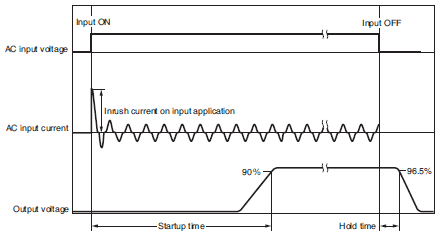
Inrush current Values for a cold start at 25°C.
Refer to Inrush Current, Startup Time, and Output Hold Time on catalog for
details.
Output
characteristics
Voltage
adjustment
range
If the output voltage adjuster (V. ADJ) is turned, the voltage will increase by
more than of the voltage adjustment range.
When adjusting the output voltage, confirm the actual output voltage from
the product and be sure that the load is not damaged.
Ripple noise
voltage
The value is when both rated output voltage and rated output current are
satisfied.
A characteristic when the ambient operating temperature is 25°C.
Static input
variation
influence
This is the maximum variation in the output voltage when the input voltage
is gradually changed within the allowable input voltage range at the rated
output voltage and rated output current.
Load variation
influence
100 to 240 VAC input, in the range of 0 A to the rated output current.
Startup time The value is when both rated output voltage and rated output current are
satisfied and at room temperature (25°C).
Refer to Inrush Current, Startup Time, and Output Hold Time on catalog for
details.
Hold time The value is when both rated output voltage and rated output current are
satisfied and at room temperature (25°C).
Refer to Inrush Current, Startup Time, and Output Hold Time on catalog for
details.
Environment Ambient
operating
temperature
At -40 to -25°C, time will be required before the rated output voltage is
output after the input voltage is input. Also, the ripple noise value may
exceed the value shown in the above table.
Reliability MTBF MTBF is calculated according to JEITA RCR-9102.
MTBF stands for Mean Time Between Failures, which is calculated
according to the probability of accidental device failures, and indicates
reliability of devices.
Therefore, it does not necessarily represent a life of the product.
Life
expectancy
Refer to Recommended Replacement Periods and Periodic Replacement
for Preventive Maintenance on catalog for details


Communication and Indication Items

Item Communication * Indication
monitor *
Resolution Data
update
cycle
Details
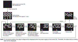
Output voltage
measurement
Yes Yes 0.1 V 5 ms Measurement accuracy
±2% (percentage of
output voltage value)
±1 digit
Output current
measurement
Yes Yes 0.1 A 5 ms Measurement accuracy
±5% (percentage of
rated output current)
±1 digit
Peak hold current measurement Yes Yes 0.1 A 5 ms Measurement accuracy
±5% (percentage of
rated output current)
±1 digit
Years until
replacement
Yes Yes 0.1 years 1 min Range
0.0 to 15.0 years
(communication)
FUL (Full) / HLF (Half) /
0.0 to 4.9 years
(indication monitor)
Percentage until
replacement
Yes Yes 0.1% 1 min Range
0.0 to 100%
Total run time Yes Yes Communication 1 h 1 min Range
0 to 262,800 h
(communication)
0 to 263 kh
(indication monitor)
Indication
monitor
1 kh
Continuous
run time
Yes None 1 min 1 min Range
0 to 15,768,000 min
Self-diagnostics Yes Yes None None Refer to Self-Diagnostics
Function on catalog for
details.
Product model Yes None None None Product model is expressed
in ASCII code
Serial number Yes None None None Expressed in hexadecimal
(4-byte)
Firmware version Yes None None None Expressed in hexadecimal
(2-byte)
MAC address Yes None None None None
IP address Yes None None None None
IP address
setting method
Yes None None None Static IP address/BOOTP
selection


Note: For details on the communication function and setting method, refer to the Switch Mode Power Supply S8VK-X
Communication Manual (Man. No. T213).
* Communication cycle can be set from 100 to 10,000 ms. The indication update cycle is 50 ms.

Inrush Current, Startup Time, and Output Hold Time

S8VK-X Specifications 10

Note: Twice the normal inrush current will flow during parallel operation or for backup operation. Also, if crossover wiring
is used for N number of Power Supplies, an inrush current of N times the inrush current for a standalone Power Supply
will flow. Therefore, check the fusing characteristics of fuses and operating characteristics of breakers making sure that
the external fuses will not burn out and the circuit breakers will not be activated by the inrush current.

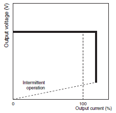
Overload Protection

When the load current reaches 121% to 160% of the rated current for S8VK-X03005-EIP, S8VK-X06012-EIP, S8VK-X06024-EIP, and S8VK-X12024[]-EIP, 101% to 110% for S8VK-X09024[]-EIP, or 151% to 165% for S8VK-X24024[]-EIP and S8VK-X48024[]-EIP, output voltage is automatically lowered to protect the Power Supply from short-circuit currents and overcurrents.
When the output current falls within the rated range, the overload protection function is automatically cleared.

S8VK-X Specifications 11

Note: 1. Internal parts may possibly deteriorate or be damaged if a short-circuited or overcurrent state continues during
operation.
2. Internal parts may possibly deteriorate or be damaged if the Power Supply is used for applications with frequent
inrush current or overloading at the load end. Do not use the Power Supply for such applications.

Overvoltage Protection

Overvoltage will be detected to prevent the load from being subjected to excessive voltage when the feedback circuit in the Power Supply fails, etc.
If an excessive voltage that is approximately 130% of the rated output voltage (but approximately 110% of the rated output voltage for only the S8VK-X09024[]-EIP) or more is output, the output voltage is shut OFF.
Reset the input power by turning it OFF for at least three minutes and then turning it back ON again.
Note: Do not turn ON the power again until the cause of the overvoltage has been removed.

Communication Specifications

Item Specification
Media access method CSMA/CD
Modulation system Baseband
Topology Star configuration
Transmission speed 100 Mbps
Transmission medium Twisted pair cable (with shield: STP): Category 5, 5e or above
Maximum transmission distance
(distance between hub and node)
100 m
Tag data
Link
Class1 Connection resource: 1 max.
Number of connected nodes 1
Number of tag sets 1
Packet interval (RPI) 100 to 10,000 ms
Time-out value Multiple of RPI
Connection type Point To Point Connection (fixed)
Explicit
Message
Class3 Number of clients that can communicate at one time: 2 max.
UCMM Number of clients that can communicate at one time: 2 max.
Modbus
message
Modbus TCP Number of clients that can communicate at one time: 2 max.
Factory
default
values
IP address 192.168.250.20
Subnet mask 255.255.255.0
Default gateway 0.0.0.0
IP address setting method Static IP address


Module Status and Network Status Indicators

Name Color Status Operating status
Module status
Indicator (MS)
Green Lit Normal
Flashing
Red Lit RAM abnormality, EEPROM abnormality
Flashing Voltage measurement abnormality,
current measurement abnormality
Not lit No power supply
Green/Red Flashing When power is turned ON
Network status
Indicator (NS)
Green Lit Connection established
Flashing Connection not established
Red Lit Multiple IP addresses
Flashing Connection timeout
BOOTP server connection abnormality
Not lit No power supply
Green/Red Flashing When power is turned ON


Communication Reset Function

This function temporarily resets the communication settings to their factory default values. Use this function when the IP address previously set is no longer known and communication is not possible.

Setting Method

(1) With the reset key pressed, turn on the power supply.
(2) Continue to hold the reset key for 10 seconds.
While pressed, an alarm indicator will flash in 0.5-second intervals.
(For models with an indication monitor, the main display and operation indicator will also repeatedly turn all indicators
on and off in 0.5-second intervals.)
(3) After 10 seconds have elapsed, the system shifts into the communication reset state, and the communication setting
values temporarily reset to their factory default values.
In the communication reset state, the alarm indicator will flash in 1-second intervals. (For models with an indication
monitor, the main display and operation indicator will return to normal operation.)
(4) In the communication reset state, reset the communication settings from the host device.
(5) After setting, turn on the power supply once again, and confirm that the set values have been changed.

Note: 1. After confirming that the product output indicator has turned off, turn on the power supply once again.
2. The only way to exit the communication reset state is to restart the power supply.
3. If you do not change the communication settings during step (4), settings will return to their prior values once
the communication reset is ended.

Switching Indications

All indicators of the indication monitor will be lit for 1 second when power is turned on. After that, each status can be displayed using the Indication switching key.

Peak Hold Current

The output current maximum value is stored as the peak hold current. (5 ms average value)
Measurement is not performed for approximately 3 seconds immediately after the input power is turned ON.

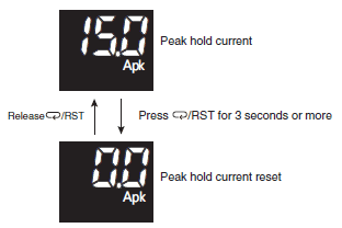
Peak Hold Curmrent Reset

When the peak hold current is displayed, it can be reset by pressing the Reset key for 3 seconds or more.

S8VK-X Specifications 20

Note: For types without an indication monitor, it is not possible to reset the peak hold current via reset key operation.

Replacement Time Calculation Function

This Power Supply is equipped with electrolytic capacitors. The electrolyte inside the electrolytic capacitors penetrates the sealing rubber and evaporates as time passes after it is manufactured. This causes deterioration of characteristics, such as decreasing the capacitance. Due to this deterioration of the characteristics of the electrolytic capacitor, this Power Supply decreases its performance as time passes. The replacement time calculation function calculates an approximate period left for maintenance of this Power Supply due to deterioration of electrolytic capacitors. Use this function to know the approximate replacement time of the Power Supply.

Note: The replacement time calculation function indicates an approximate period left for maintenance, based on deterioration
of the electrolytic capacitors. It does not predict failures resulting from other causes.

Principle of Operation

The deterioration speed of the electrolytic capacitors varies considerably with the ambient temperature. (Generally the speed follows the Arrhenius Law, i.e., for every 10°C increase in the temperature, the rate of degradation doubles.) The S8VK-X monitors the temperature inside the Power Supply, and calculates the amount of deterioration according to the running hours and internal temperature.

Note: 1. Due to degradation of internal electronic parts, replace the Power Supply approximately 15 years after purchase
even if the replacement time calculation for years and percentage do not appear.
2. The replacement time is accelerated or decelerated according to operating conditions. Periodically check
indication.
3. The accuracy of the replacement time calculation function will be reduced in applications where the input power
turns ON and OFF frequently.

Years until replacement

(Indication monitor)
3687_sp_13 is indicated at the time of purchase (when initially powered on), and continues to be indicated for approximately one month.
Afterward, the state of deterioration for the electrolytic capacitor is calculated based on the usage environment, and 3687_sp_14 is indicated when deterioration progresses. When the years until replacement reaches 5 years or less, it is indicated in 0.1 step increments within the range of 4.9 to 0.0. (Depending on the usage environment, the number of years may be indicated after 3687_sp_13 without 3687_sp_14 being indicated.)
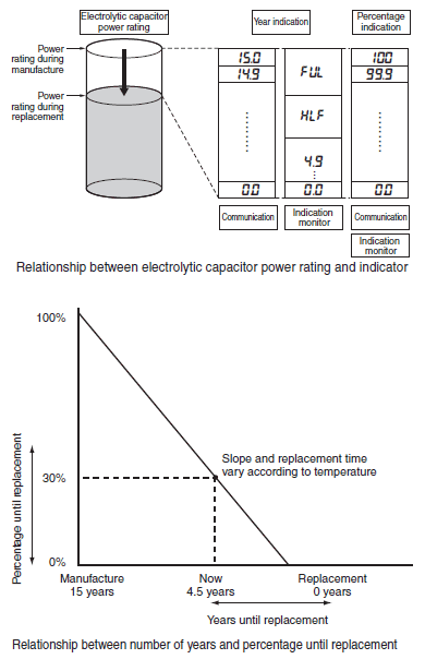
(Communication)
Communication is calculated in 0.1 step increments within a range of 15.0 to 0.0.

Note: The number of years until replacement may vary if there are frequent load variations or in locations where the ambient
temperature fluctuates drastically.

Percentage until replacement

With the number of years until replacement at the time of manufacture set as 100%, as deterioration of the electrolytic capacitor progresses through use, it decreases in 0.1% step increments.

S8VK-X Specifications 25

Difference between Expected Life and Replacement Time

OMRON calculates the expected life based on the following conditions.
1.Rated input voltage
2. Load rate: 50%
3. Ambient temperature: +40°C
4. Standard mounting

Note: As the values were calculated using an aluminum electrolytic condenser temperature rise test, they are not
guaranteed. Use this data as a reference for maintenance and replacement time calculation.

The expected life span of the S8VK-X is 10 years minimum.
Also, a replacement time calculation function is included among the functions of the S8VK-X. The replacement time is the service life (the Power Supply’s internal temperature is monitored at all times) of the internal electrolytic capacitor in actual operating conditions, and varies according to the customers operating conditions. 15 years is taken as the maximum period of the maintenance forecast.

Total Run Time

The accumulated value of the product’s time powered on is measured as the total run time.
(With indication monitor)
Total run time increases in 3687_sp_16 (kh) steps with use.
(Communication)
Total run time increases in 3687_sp_16 (h) steps with use.

Time Chart

S8VK-X Specifications 28

Note: 1. The total run time does not include the time that the Power Supply is OFF.
2. The total run time measures the total time that power is being supplied and is not related in any way to deterioration
in the electrolytic capacitor built into the Power Supply or to the effects of the ambient temperature.

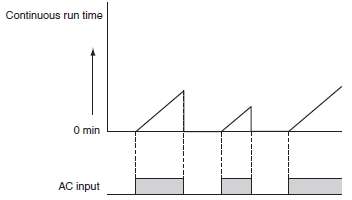
Continuous Run Time (Communication Only)

The product’s time powered on is measured as continuous run time, and the continuous run time increases in 1 (min) steps with use.
Continuous run time will be reset when power is turned off.

Time Chart

S8VK-X Specifications 30

Note: 1. The continuous run time does not include the time that the Power Supply is OFF.
2. The continuous run time measures the total time that power is being supplied and is not related in any way to
deterioration in the electrolytic capacitor built into the Power Supply or to the effects of the ambient temperature.

Model S8VK-X06024-EIP, S8VK-X09024-EIP, S8VK-X12024-EIP, S8VK-X24024-EIP, S8VK-X48024-EIP


Weight N/A
Model

S8VK-X06024-EIP, S8VK-X09024-EIP, S8VK-X12024-EIP, S8VK-X24024-EIP, S8VK-X48024-EIP

Related products