USD 333.84
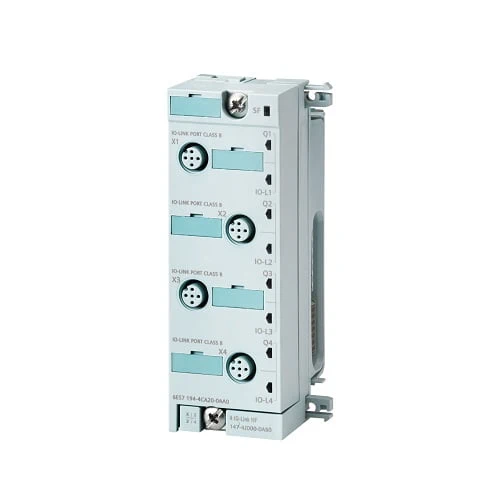
The 4 IO-LINK HF electronic module facilitates data exchange with up to 4 IO-Link devices.
Since IO-Link is compatible with standard sensors, commercially available sensors in accordance with IEC 61131 Type 1 can also be operated on the IO-Link master.
| Article number | 6ES7147-4JD00-0AB0 | |
| ET200pro, EM 4 IO-Link HF | ||
| Supply voltage | ||
| Rated value (DC) | 24 V | |
| Reverse polarity protection | Yes | |
| Load voltage 2L+ | ||
| ● Rated value (DC) | 24 V | |
| ● Short-circuit protection | Yes | |
| ● Reverse polarity protection | Yes; against destruction; load increasing | |
| Input current | ||
| from supply voltage 1L+, max. | 40 mA | |
| from load voltage 2L+ (without load), max. | 20 mA | |
| from backplane bus 3.3 V DC, max. | 20 mA | |
| Encoder supply | ||
| Number of outputs | 4 | |
| Short-circuit protection | Yes; per module, electronic | |
| Output current | ||
| ● up to 55 °C, max. | 2 A | |
| Power loss | ||
| Power loss, typ. | 2.6 W | |
| IO-Link | ||
| Number of ports | 4 | |
| ● of which simultaneously controllable | 4 | |
| IO-Link protocol 1.0 | Yes | |
| IO-Link protocol 1.1 | Yes | |
| Transmission rate | 4.8 kBaud (COM1); 38.4 kBaud (COM2), 230.4 kBaud (COM3) | |
| Size of process data, input per port | 32 byte | |
| Size of process data, input per module | 32 byte | |
| Size of process data, output per port | 32 byte | |
| Size of process data, output per module | 32 byte | |
| Memory size for device parameter | 2 kbyte; for each port | |
| Master backup | Possible with function block IO_LINK_MASTER | |
| Configuration without S7-PCT | Possible; autostart/manual function | |
| Cable length unshielded, max. | 20 m | |
| Operating modes | ||
| ● IO-Link | Yes | |
| ● DI | Yes | |
| ● DQ | Yes; max. 100 mA | |
| Connection of IO-Link devices | ||
| ● Port type A | Yes; via 3-core cable | |
| ● Port type B | Yes; Additional device supply: for X1 and X2 max. 2 A in total, for X3 and X4 max. 2 A in total | |
| Interrupts/diagnostics/status information | ||
| Diagnostics function | Yes | |
| Alarms | ||
| ● Diagnostic alarm | Yes | |
| Diagnoses | ||
| ● Diagnostic information readable | Yes | |
| ● Wire-break | Yes; channel by channel | |
| ● Short-circuit | Yes; channel by channel | |
| Diagnostics indication LED | ||
| ● Channel status display | Yes; One green LED for channel status Qn (SIO mode) and port status IO-Ln (IO-Link mode) | |
| ● Group error SF (red) | Yes | |
| ● Channel fault indicator F (red) | Yes; combined with the IO-Link port status | |
| Potential separation | ||
| between the load voltages | Yes | |
| between backplane bus and all other circuit components | Yes | |
| Potential separation channels | ||
| ● between the channels | No | |
| Isolation | ||
| Isolation tested with | 707 V DC (type test) | |
| Degree and class of protection | ||
| IP degree of protection | IP65/67 | |
| Standards, approvals, certificates | ||
| Suitable for safety-related tripping of standard modules | No | |
| Dimensions | ||
| Width | 45 mm | |
| Height | 130 mm | |
| Depth | 35 mm | |
| Weights | ||
| Weight, approx. | 150 g | |