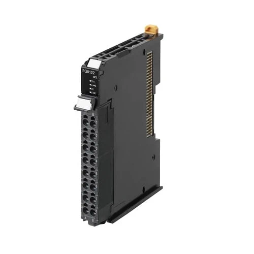
NX-Series – NX-PG0[][][] – Omron Position Interface Unit
USD $ 245.09
Omron produce industrial sensors range such as fiber sensors, photoelectric sensors, displacement sensors/ measurement sensors, proximity sensors, photomicro sensors and rotary encodes.
Features
• The MC Function Modules of the NJ/NX/NY5 Controller allows you to connect with as many axes as the NJ/NX/NY5 Controller can control
• High-speed remote I/O control with communications cycle as fast as 125 μs*1
• Free-run refreshing or task period prioritized refreshing*2 with the EtherCAT Coupler Unit
• Latching (2 external latch inputs)
• Open collector pulse outputs up to 500 kHz or line driver pulse outputs up to 4 MHz
• Line driver output models with two or four channels
*1. When using the NX-EC01[][] together with the NX701-[][][][] and NX-ECC203.
*2. Task Period Prioritized refreshing is available when the NX-ECC203 is used together.
Sysmac is a trademark or registered trademark of OMRON Corporation in Japan and other countries for OMRON factory automation products.
EtherCAT® is a registered trademark and patented technology, licensed by Beckhoff Automation GmbH, Germany. EtherNet/IP™ is a trademark of ODVA.
Other company names and product names in this document are the trademarks or registered trademarks of their respective companies.
Lineup
Applicable standards
Refer to the OMRON website (www.ia.omron.com) or ask your OMRON representative for the most recent applicable standards for each model.
Position Interface: Pulse Output Units
| Product name |
Specification | Model | ||||||
|---|---|---|---|---|---|---|---|---|
| Number of chan- nels *1 |
External inputs |
External outputs |
Maximum pulse output speed |
I/O refreshing method |
Number of I/O entry mappings |
Control output interface |
||
| Pulse Output Unit  |
1 (NPN) |
2 (NPN) | 1 (NPN) | 500 kpps | • Synchro- nous I/O refreshing • Task period prioritized refreshing *2 |
1/1 | Open collector output |
NX-PG0112 |
| 1 (PNP) |
2 (PNP) | 1 (PNP) | NX-PG0122 | |||||
| 2 | 5 inputs/ CH (NPN) |
3 outputs/ CH (NPN) |
4 Mpps | 2/2 | Line driver output |
NX-PG0232-5 | ||
| 5 inputs/ CH (PNP) |
3 outputs/ CH (PNP) |
NX-PG0242-5 | ||||||
| 4 | 5 inputs/ CH (NPN) |
3 outputs/ CH (NPN) |
4/4 | NX-PG0332-5 | ||||
| 5 inputs/ CH (PNP) |
3 outputs/ CH (PNP) |
NX-PG0342-5 | ||||||
*1. This is the number of pulse output channels.
*2. Unit version 1.2 or later and an NX-ECC203 EtherCAT Coupler Unit are required.
Cables and Connectors for Line Driver Output Units with MIL Connectors
| Product name |
Specifications | Model | |
|---|---|---|---|
| Connector-Terminal Block Conversion Unit |
Flat Cable Connectors type (Terminal block with M3 screws) 34-terminals |
 |
XW2B-34G4 |
| Flat Cable Connectors type (Terminal block with M3.5 screws) 34-terminals |
 |
XW2B-34G5 | |
| MIL Connectors type (Slim Connector) 34-terminals |
 |
XW2D-34G6 | |
| MIL Connectors type (Phillips screw) 34-terminals |
 |
XW2R-J34GD-T | |
| MIL Connectors type (Slotted screw (rise up)) 34-terminals |
 |
XW2R-E34GD-T | |
| MIL Connectors type (Push-in spring) 34-terminals |
 |
XW2R-P34GD-T | |
| Cable for Connector-Terminal Block Conversion Unit |
MIL Connectors type 34-terminals |
Cable length: 0.5 m | XW2Z-050EE |
| Cable length: 1 m | XW2Z-100EE | ||
| Cable length: 1.5 m | XW2Z-150EE | ||
| Cable length: 2 m | XW2Z-200EE | ||
| Cable length: 3 m | XW2Z-300EE | ||
| Cable length: 5 m | XW2Z-500EE | ||
Note: Each of NX-PG0232-5 and NX-PG0242-5 has one MIL connector. Therefore, one Connector-Terminal Block Conversion Unit is required.
Each of NX-PG0332-5 and NX-PG0342-5 has two MIL connectors. Therefore, two Connector-Terminal Block Conversion Units are required.
Option
| Product name | Specification | Model |
|---|---|---|
| Unit/Terminal Block Coding Pins | For 10 Units (Terminal Block: 30 pins, Unit: 30 pins) | NX-AUX02 |
| Product name | Specification | Model | |||
|---|---|---|---|---|---|
| No. of terminals |
Terminal number indications |
Ground terminal mark |
Terminal current capacity |
||
| Terminal Block | 16 | A/B | None | 10 A | NX-TBA162 |
Accessories
Not included.
SPECIFICATIONS
General Specification
| Item | Specification | |
|---|---|---|
| Enclosure | Mounted in a panel | |
| Grounding method | Ground to less than 100 Ω | |
| Operating environment |
Ambient operating temperature |
0 to 55°C |
| Ambient operating humidity |
10% to 95% (with no condensation or icing) | |
| Atmosphere | Must be free from corrosive gases. | |
| Ambient storage temperature |
-25 to 70°C (with no condensation or icing) | |
| Altitude | 2,000 m max. | |
| Pollution degree | Pollution degree 2 or less: Meets IEC 61010-2-201. | |
| Noise immunity | Conforms to IEC61000-4-4, 2 kV (power supply line) | |
| Overvoltage category | Category II: Meets IEC 61010-2-201. | |
| EMC immunity level | Zone B | |
| Vibration resistance | Conforms to IEC 60068-2-6. 5 to 8.4 Hz with 3.5-mm amplitude, 8.4 to 150 Hz, acceleration of 9.8 m/s2, 100 min each in X, Y, and Z directions (10 sweeps of 10 min each = 100 min total) |
|
| Shock resistance | Conforms to IEC 60068-2-27. 147 m/s2, 3 times each in X, Y, and Z directions | |
| Applicable standards * | cULus: Listed (UL508) or Listed (UL 61010-2-201), ANSI/ISA 12.12.01, EU: EN 61131-2, C-Tick or RCM, KC Registration, NK, LR |
|
* Ask your OMRON representative for the most recent applicable standards for each model.
Pulse Output Unit Specifications
Pulse Output Unit (Open collector output, PNP type) NX-PG0122
| Unit name | Pulse Output Unit | Model | NX-PG0122 | |
|---|---|---|---|---|
| Number of axes | 1 | Type of external connections |
Screwless push-in terminal block (16 terminals) |
|
| I/O refreshing method *1 | Synchronous I/O refreshing or task period prioritized refreshing | |||
| Indicators |  |
I/O signals | Inputs: 2, External inputs *2 Outputs: 3, The outputs are the forward direction pulse output, reverse direction pulse output, and external output *3 (one of each output). |
|
| Control method | Open-loop control through pulse string output | |||
| Controlled drive | Servo drive with a pulse train input or a stepper motor drive | |||
| Pulse output form | Open collector output | |||
| Control unit | Pulses | |||
| Maximum pulse output speed |
500kpps | |||
| Pulse output method | Forward/reverse direction pulse outputs or pulse + direction outputs | |||
| Position control range | -2,147,483,648 to 2,147,483,647 pulses | |||
| Velocity control range | 1 to 500,000 pps | |||
| Positioning *2 | ||||
| Single-axis position control |
Absolute positioning, relative positioning, and interrupt feeding | |||
| Single-axis velocity control |
Velocity control (velocity feeding in Position Control Mode) | |||
| Single-axis synchronized control |
Cam operation and gear operation | |||
| Single-axis manual operation |
Jogging | |||
| Auxiliary function for single-axis control |
Homing, stopping, and override changes | |||
| External input specifications | ||||
| Input voltage | 20.4 to 28.8 VDC (24 VDC +20%/-15%) |
ON voltage/ ON current |
15 VDC min./3 mA min. | |
| Input current | 4.6 mA typical (24 VDC) | OFF voltage/OFF current |
4.0 VDC max./1 mA max. | |
| ON/OFF response time | 1 μs max./2 μs max. | |||
| Internal I/O common processing |
PNP | |||
| External output specifications | ||||
| Rated voltage | 24 VDC | |||
| Load voltage range | 15 to 28.8 VDC | Residual voltage | 1.0 V max. | |
| Maximum load current | 30mA | Leakage current | 0.1 mA max. | |
| ON/OFF response time | Pulse output: Refer to “NX-series Position Interface Units User’s Manual (W524-E1)”. 5 μs max./5 μs max. |
|||
| Internal I/O common processing |
PNP | |||
| Dimensions | 12 × 100 × 71 mm (W×H×D) |
Isolation method |
External inputs: Photocoupler isolation External outputs: Digital isolator |
|
| Insulation resistance | 20 MΩ min. between isolated circuits (at 100 VDC) |
Dielectric strength |
510 VAC between isolated circuits for 1minute with leakage current of 5 mA max. |
|
| I/O power supply source | Supplied from the NX bus. 20.4 to 28.8 VDC (24 VDC +20%/-15%) |
Current capacity of I/O power supply terminals |
IOV: 0.1 A max. per terminal IOG: 0.1 A max. per terminal |
|
| NX Unit power consumption |
• Connected to a CPU Unit 1.30 W max. • Connected to a Commu- nications Coupler Unit 0.90 W max. |
Current consumption from I/O power supply |
20 mA max. | |
| Weight | 70 g max. | Cable length | 3 m max. | |
| Circuit layout | 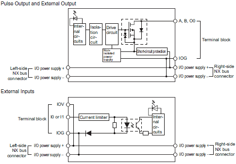 |
|||
| Installation orientation and restrictions |
Installation orientation: • Connected to a CPU Unit: Possible in upright installation. • Connected to a Communications Coupler Unit: Possible in 6 orientations. Restrictions: There are no restrictions. |
|||
| Terminal connection diagram |
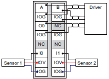 |
|||
| Failure detection | None | Protection | None | |
*2. You can use the external inputs as latch inputs.
*3. You can use the external output as error counter reset outputs.
*4. These functions are supported when you also use the MC Function Module in the NJ/NX-series CPU Unit or the NY- series Industrial PC.
For details, refer to the motion control user’s manual for the connected CPU Unit or Industrial PC.
A Pulse Output Unit only outputs pulses during the control period based on commands received at a fixed period.
Target position calculations (distribution calculations) for acceleration/deceleration control or for each control period must be performed on the Controller.
Version Information
Connected to a CPU Unit
Refer to the user’s manual for the CPU Unit details on the CPU Units to which NX Units can be connected.
| NX Unit | Corresponding unit versions/versions | ||
|---|---|---|---|
| Model | Unit version | CPU Unit | Sysmac Studio |
| NX-PG0112 | Ver. 1.1 | Ver.1.13 | Ver. 1.17 |
| Ver. 1.2 | |||
| Ver. 1.3 | Ver. 1.19 | ||
| NX-PG0122 | Ver. 1.0 | Ver.1.13 | Ver. 1.17 |
| Ver. 1.1 | |||
| Ver. 1.2 | |||
| Ver. 1.3 | Ver. 1.19 | ||
| NX-PG0232-5 | Ver. 1.2 | Ver.1.13 | Ver. 1.17 |
| Ver. 1.3 | Ver. 1.19 | ||
| NX-PG0242-5 | Ver. 1.2 | Ver.1.13 | Ver. 1.17 |
| Ver. 1.3 | Ver. 1.19 | ||
| NX-PG0332-5 | Ver. 1.2 | Ver.1.13 | Ver. 1.17 |
| Ver. 1.3 | Ver. 1.19 | ||
| NX-PG0342-5 | Ver. 1.2 | Ver.1.13 | Ver. 1.17 |
| Ver. 1.3 | Ver. 1.19 | ||
Note: Some Units do not have all of the versions given in the above table. If a Unit does not have the specified version, support is provided by the oldest available version after the specified version. Refer to the user’s manuals for the specific Units for the relation between models and versions.
Connected to an EtherCAT Coupler Unit
| NX Unit | Corresponding unit versions/versions | |||
|---|---|---|---|---|
| Model | Unit version | EtherCAT Coupler Unit |
CPU Unit or Industrial PC | Sysmac Studio |
| NX-PG0112 | Ver. 1.1 | Ver. 1.0 | Ver. 1.05 | Ver. 1.10 |
| Ver. 1.2 | Ver. 1.3 *2*4 | Ver. 1.13 | ||
| Ver. 1.3 | Ver. 1.19 | |||
| NX-PG0122 | Ver. 1.0 | Ver. 1.0 | Ver. 1.05 | Ver. 1.06 |
| Ver. 1.1 | Ver. 1.08 | |||
| Ver. 1.2 | Ver. 1.3 *2*4 | Ver. 1.13 | ||
| Ver. 1.3 | Ver. 1.19 | |||
| NX-PG0232-5 | Ver. 1.2 | Ver. 1.3 *2*4 | Ver. 1.05 | Ver. 1.15 |
| Ver. 1.3 | Ver. 1.19 | |||
| NX-PG0242-5 | Ver. 1.2 | Ver. 1.3 *2*4 | Ver. 1.05 | Ver. 1.15 |
| Ver. 1.3 | Ver. 1.19 | |||
| NX-PG0332-5 | Ver. 1.2 | Ver. 1.3 *2*4 | Ver. 1.05 | Ver. 1.15 |
| Ver. 1.3 | Ver. 1.19 | |||
| NX-PG0342-5 | Ver. 1.2 | Ver. 1.3 *2*4 | Ver. 1.05 | Ver. 1.15 |
| Ver. 1.3 | Ver. 1.19 | |||
Note: Some Units do not have all of the versions given in the above table. If a Unit does not have the specified version, support is provided by the oldest available version after the specified version. Refer to the user’s manuals for the specific Units for the relation between models and versions.
*1. You can use the following versions if time stamp refreshing is not used.
*2. To use task period prioritized refreshing, you must use the NX-ECC203.
*3. If you do not use task period prioritized refreshing, you can use EtherCAT Coupler Units which support Position Interface Units with unit version 1.1 or earlier.
*4. If you do not use task period prioritized refreshing, you can use EtherCAT Coupler Units with unit version 1.0.
Connected to an EtherNet/IP Coupler Unit
| NX Unit | Corresponding unit versions/versions | ||||||
|---|---|---|---|---|---|---|---|
| Model | Unit version |
Application with an NJ/NX/NY-series Controller *1 |
Application with a CS/CJ/CP-series PLC *2 | ||||
| EtherNet/IP Coupler Unit |
CPU Unit or Industrial PC |
Sysmac Studio |
EtherNet/IP Coupler Unit |
Sysmac Studio |
NX-IO Configurator *3 |
||
| NX-PG0112 | Ver. 1.1 | — | — | — | — | — | — |
| Ver. 1.2 | |||||||
| Ver. 1.3 | |||||||
| NX-PG0122 | Ver. 1.0 | — | — | — | — | — | — |
| Ver. 1.1 | |||||||
| Ver. 1.2 | |||||||
| Ver. 1.3 | |||||||
| NX-PG0232-5 | Ver. 1.2 | — | — | — | — | — | — |
| Ver. 1.3 | |||||||
| NX-PG0242-5 | Ver. 1.2 | — | — | — | — | — | — |
| Ver. 1.3 | |||||||
| NX-PG0332-5 | Ver. 1.2 | — | — | — | — | — | — |
| Ver. 1.3 | |||||||
| NX-PG0342-5 | Ver. 1.2 | — | — | — | — | — | — |
| Ver. 1.3 | |||||||
Note: 1. Some Units do not have all of the versions given in the above table. If a Unit does not have the specified version, support is provided by the oldest available version after the specified version. Refer to the user’s manuals for the specific Units for the relation between models and versions.
Note: 2. You cannot connect the relevant NX Unit or use the relevant NX Unit function if “—” is shown in the corresponding unit versions/versions column.
*1. Refer to the user’s manual of the EtherNet/IP Coupler Unit for the unit versions of EtherNet/IP Units corresponding to EtherNet/IP Coupler Units.
*2. Refer to the user’s manual of the EtherNet/IP Coupler Unit for the unit versions of CPU Units and EtherNet/IP Units corresponding to EtherNet/IP Coupler Units.
*3. For connection to an EtherNet/IP Coupler Unit with unit version 1.0, connection is supported only for a connection to the peripheral USB port on the EtherNet/IP Coupler Unit. You cannot connect by any other path. If you need to connect by another path, use an EtherNet/IP Coupler Unit with unit version 1.2 or later.

